Help. Little black wire

Hicksi

New member
Hey Guys,

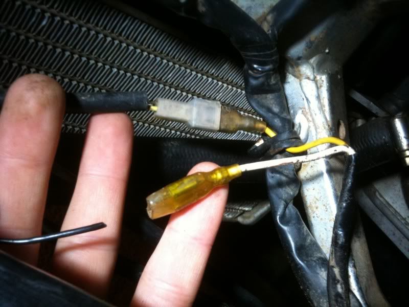
In one of my earlier threads i pointed out this small black wire, and i have no idea where its come from?

Picture 1.
IMG_2446.jpg


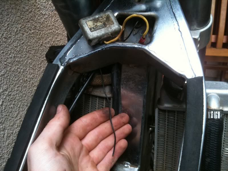
I had ago at opening up the loom this evening, hoping to locate it, but i could really do with some help.

Picture 2.
IMG_2513.jpg


The black wire in picture 1 is by my thumb, the one that goes off to the left, it joins with two other wires that come from both front indicator wires, and the connector block that goes up to the LHS controls.

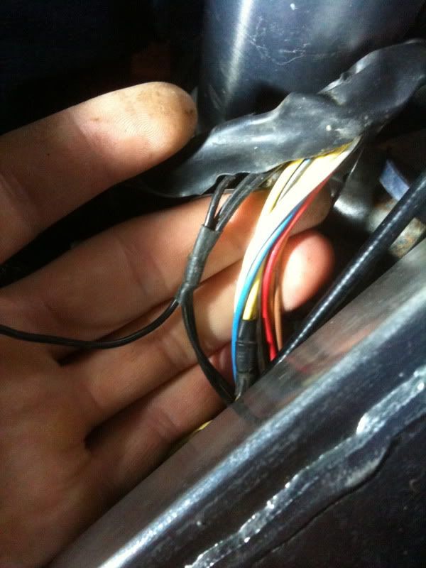
The other two wires go down, one is the earth that attaches to the Voltage Regulator that sits in the recess by the headstock, the other continues down the loom with a collection of other wires that can be seen in picture 3. (Ones im not holding with thumb)

Picture 3.
IMG_2518.jpg


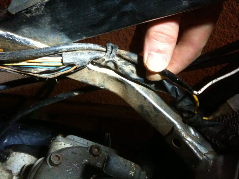
The two cables that im holding with my thumb have a white and yellow wire, each with a spade connector, the white one is un-connected (shown in picture 4.)

IS THIS WHERE THE WIRE IN PICTURE ONE CONNECTS TO?

Otherwise, where the hell does that little black wire go to? should it have a ring end on and just be earthed to the frame?

Please help me locate this wire :confused:

Thanks guys
 
That white cable is likely the full power output from lighting coil. You don't want to connect it to chassis ground.
 
Thanks for the response bergerhag!

I will have another look today, but i think your right, the white and yellow wires stem from the lighting coil.

BUT, does anyone know what this white wire connects to?

Is it likely that this connects to the little black wire?
 
I think you can probably check that black wire for continuity to ground, but everything in the photos and your description indicates it's a ground wire. I would ground it (redundant ground)for the time being and remember it's there if/when you find a device that needs a ground.

I wouldn't connect the black wire to the white wire with anything smaller than a headlight.

-dean
not an expert
 
Yellow from stator is a center output from light coil. This is done to save the ac regulator when not running big headlights. If you connect high power lamps, or maybe an extra outlet for helmet lights, you can disconnect the yellow, and connect the whithe were the yellow was to benefit from full lighting coil power.
 
Right ok!

So correct me if im wrong.

I bought the bike in this state, with no lights, horn, flashers etc hooked up, and the yellow output wire connected.

Im putting it back on the road, i.e. wiring in the headlamp, horn, flashers etc... So i need to disconnect the yellow wire, and connect the white in order for it to work?

BUT,

This still doesn't explain the little black wire??? Im still thinking this is some sort of negative/earth wire? But where the hell does it go?
 
I can't tell you where it goes; the only way to find out is to cut open the sheath on the wiring loom and follow it. There are often connections made INSIDE the sheath that are not visible. In some cases the wire actually changes colour inside the sheath.

If any aftermarket switches were previously used, their colours were different than the factory colours.
 
Motogroove & Neil E:

Think your both right, it DOES look like a ground? ive traced it up the sheath to both the right and left indicators, and up towards the LHS hand controls.

How would i test it for continuity? Do i really need to do that?

Recon ill just add a ring connector, and fix it to a bolt on the chassis for now.

Bergerhag:

Still need to know if i have to connect the white wire, and disconnect the yellow in order to run the lights etc?

At the end of the day, is there any fuses i can blow by messing around with this stuff?
 
Motogroove & Neil E:

How would i test it for continuity? Do i really need to do that?

Recon ill just add a ring connector, and fix it to a bolt on the chassis for now.
?

Actually, testing for continuity might mislead you if your mysterious end is the place that's supposed to ground everything. But it sounds like one of the black ones in picture 2 is grounded, and that they are all connected. So, visual inspection should probably tell you enough.

As far as testing for continuity, I wanted to do that for certain components and locations when I powdercoated my frame, so I could be sure the grounds that look good are actually good.
I used an ohm meter, looking for zero resistance. i.e. touch the two probes on the meter to each other and the meter goes to zero. That's what you want to see between the ground tested item and some other good known ground. No change at all in the meter means no connection. Something in between means a bad connection .
 
Unless you are preparing for maximum output for lights use, you can leave the yellow as it is and the white disconnected. Std lightning application does not require full output from coil.
 
Thanks guys.

Ill continue with the std lighting set-up (yellow wire) for now.

Just slightly confused with what was said over the black wire, its grounded further up (as i stated earlier), does this mean i can just tape the end up and leave it, or should i ground it as well to be sure?
 
Back
Top