ignition side breather / drain - ideas ?

Caravan Monster

New member
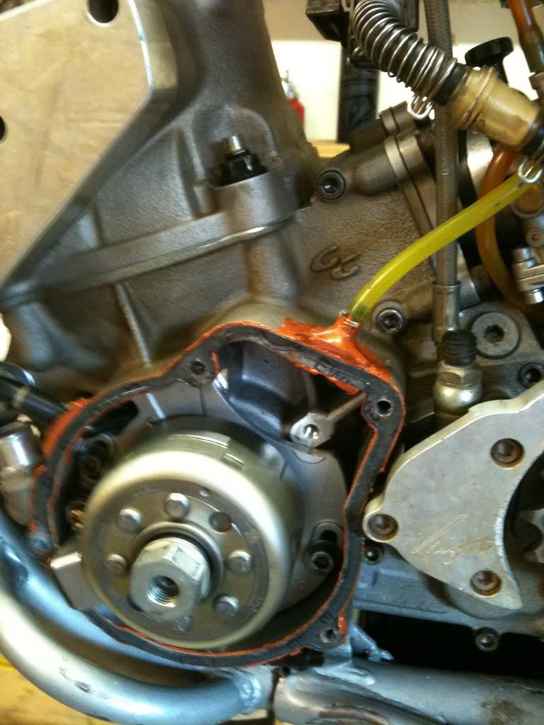
Purchased an '06 EC200 at the weekend. Got it home, and upon examination it became evident that the ignition side main bearing had failed :( Got the engine out, stripped down and cleaned to rebuild. I've not split EC engine cases before and didn't realise that there is a drain hole from the generator housing and down through the (M6?) threaded hole in the underside of the cases.

This set up looks like a recipe for disaster to me because it will fill up the housing with water when fording rivers and suchlike. The Gas Gas diagrams show that the drain hole is not sealed with a bolt and washer as standard. Does anyone know why this is so, and would there be any harm in blocking the hole ?

Nails to show path of the drain :D


Showing the river silt that wrecked the bearing seal

 
Hmmmm... I just saw that hole when I had mine apart but never investigated where it went. Interesting... But from my experience I question whether that's where your silt came from.

The ignition side on my '05 is always clean and dry after following GMP's suggestions for sealing the case. Don't know for sure about the '06 but on the '05 and earlier models there is also an open drain in the plastic cover at 6 o-clock. I sealed that with RTV silicone, sealed the rubber grommets, and ran a vent line thru the 2 0-clock grommet up under the seat by the CDI.

Also from GMP: (credit where credit's due) those plastic cases tend to distort with too much tightening torque and don't seal well. To solve this double up the gaskets. Glue them both to the case with a thin bead of RTV. Then lightly grease the mating edge of the plastic cover to prevent it from sticking to the outer gasket and install being careful not to overtorque. You get a much better seal and can still remove the cover after a wet ride to dry out/clean without damaging the gaskets. Like I said mines been set up that way for 4 years and my ign. Looks like new in there. Plenty of wet rides.

I didn't seal the hole you mention but haven't had any water infiltration. Now you've got me wondering what that hole could possibly be for though. Can't see any harm in plugging it but maybe someone else has thoughts.

I know, I know, shoulda used gray RTV but this is what I had handy.

12d265e3.jpg
 
Last edited:
this must be the hole to drain the crank housing, very usefull after putting the bike under water.....

Nope. That one is more towards the front. This looks more like some kind of jig/assembly type hole to me. Can't figure any other purpose...
 
Closing the hole is not necessary if your ignition is otherwise sealed. Meaning that if air can't get out anywhere else, water shouldn't come in. If the bike is on it's side in a creek maybe you would get some water entering. If you leave both the cover drain slot open and the threaded hole open then water could move back and forth between both places.

Venting does have value because of temperature changes and the possibility of condensation. I'd say plugging the threaded hole and venting through the unused grommet is the best plan. I sealed up my cover slot and vented via the 6mm tapped hole. I made up a 90* fitting and my tubing runs up to the air box. As long as the tubing stays empty, I'm happy. I can pull the tubing off to drain it if needed.

Looking at the nails in your picture, the outlet hole going to the tapped hole is noticeably above the bottom of the ignition. So water would get quite high before getting to the tapped hole. Seal the tapped hole and vent through the grommet, then take the cover off after every deep water ride to check that the ignition is dry.
 
Thanks for the replies. I'm thinking of a similar solution. The generator wires exit at 2 o'clock on this bike and I might see if it is possible to run a length of carb vent hose through the grommet and alongside, or maybe inside the wire sheathing and up into the airbox. Then it would be possible to block off the hole in the bottom of the cases without worrying about condensation build up. I agree about the problem of overtightened and distorted ignition cover. In this case, the plastic cover is a bad way, and it might end up being necessary to get a new one.

If it's helpful, I've uploaded another picture of the cases, to show the hole in question from the other side (nails to show direction of flow):


Whilst I'm asking questions, can anyone advise how to pull the inner main roller bearing sleeve from the crank. I've only previously worked on engines with main ball bearings, so haven't encountered this problem before:

 
heat that inner race up real good, i used a Mapp gas torch. Then carefully tap a sharp cold chisel in between the crank and the race to get a gap started. then you can pry it off with a couple big screwdrivers or wedges. just keep it moving as square as possible. it actually comes off pretty easily with enough heat.

FWIW when I installed the new inner race i heated it up expecting to have to press it on there, but with the crank on it's side, when I slipped it on it fell right into place with a clink. after it cooled it tightened right up.

Another tip that you might already know... put the bearings in the freezer and heat up the cases and they also might drop right in, or at least press in real easily. manual says heat cases to 150C.
 
Aaahhh... a heating ring. So that's how the big boys do it. Looks like it might be easy enough to fab up a shade tree version... if a guy only had a lathe.... I bet the cold chisel is cheaper. :D
 
Just get a bearing/gear splitter and a puller, and yes some heat is good. Much more care is needed on install of the new part. I would freeze the crank journal with dry ice, heat the race evenly and carefully, and drive or press it on with a brass or copper pipe of the appropriate diameter.
 
Back
Top