Stator wires on o3 ec300

Dnf-init

New member
Hi, I am new to the forum and just got an 03 ec300,
How ever I am trying to sort the wiring out and have a couple
That I am not sure about and where they go.

I am sorry as I know it probably been asked a million times.
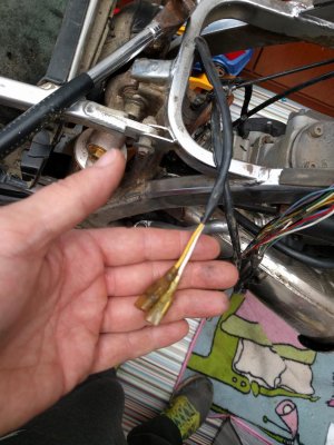
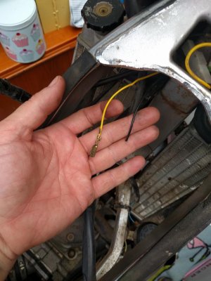
I have a yellow and a white wire coming from stator which I can't work out where they go. I also have a black and a yellow wire hanging down form near to where the voltage regulator is which seem to go to the front of the wiring loom. Can anyone pls help would be very grateful.

Many thanks nick
 

Attachments

  • 1457531003364-1818904069.jpg
    1457531003364-1818904069.jpg
    121.5 KB · Views: 78
  • 1457531038546-930965702.jpg
    1457531038546-930965702.jpg
    114.3 KB · Views: 64
Go to the GG site and download some manuals. Not every one has a wiring diagram in it, so you need to try a few. Look for one as close to your year as possible. That being said, the wiring is very similar on all years prior to the estart bikes. Your bike could have a European complete harness or a more basic harness. Someone could have removed wires too.

As to your first picture, those are the lighting output wires from the stator. One end of the stator windings is already connected to chassis ground. The yellow wire is your normal AC output for lighting. The white wire is not used unless you have estart. It delivers a bit higher AC voltage and requires a voltage regulator/rectifier unit to create DC power for battery charging.

The yellow wire connects to a voltage regulator usually mounted near the coil (or headstock on older bikes). So to make a light work you use AC power between the yellow wire and ground. The regulator clips peak voltage so you don't burn out bulbs.

ASSUMING the wires in your second picture connect to the REGULATOR, the yellow wire connects to stator yellow (and several other yellow wires taking power to different locations). The black wire should have a ring terminal on it and be connected to frame ground.

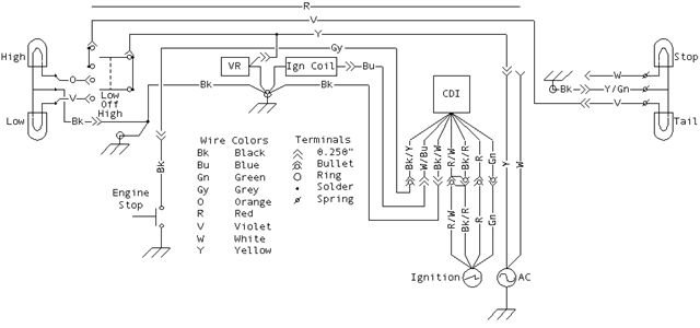
I find the GG wiring diagrams very useful; it's just a matter of following the connections and colour changes.
 
schematic

Here is a schematic diagram.
 

Attachments

  • gg-wiring.jpg
    gg-wiring.jpg
    26.8 KB · Views: 87
Back
Top