18 EC300 Battery not charging

Tech

New member
18 EC300 Battery not charging FIXED

**Regulator/Rectifier is putting out DC voltage...rising & falling w/throttle

**Relay functioning correctly

**Motor & starter running perfectly

**Battery..new AntiGravity 8 cell small case..... runs down after each ride...I sometimes have to kick start. Last ride battery was at 8.6 volts at end of ride.

Possible causes yet to be verified:

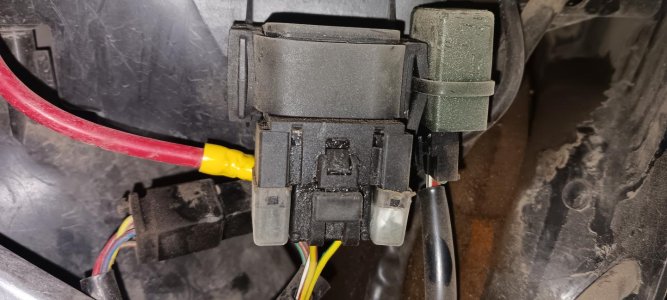
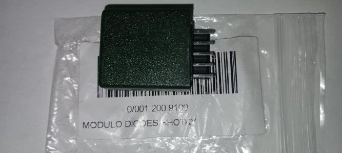
#1 Diode at relay - Below is a quote from an old thread indicating it could be the diode attached to the relay.

#2 Loose/faulty connection - I have traced most connections but could have missed something.

I know its an old thread but anyway.The Diode module is used to isolate and protect the two DC supplies ie The stator supply and the Battery supply.
The battery needs to be charged from the Stator.The Diode Module ensures the stator can only flow voltage into the Battery circuit but the battery cannot feed back into the Stator circuit (lights etc).
If you diode Module was missing your battery would not charge which is your Problem.
As for running the motor without the battery can destroy your electronics through over voltage.The battery is ,as well as being a load it acts like a regulator

I am at my wits end...& my wits are old & weak!!

Thanks everyone!!
 
Last edited:
**Regulator/Rectifier is putting out DC voltage...rising & falling w/throttle

**Relay functioning correctly

**Motor & starter running perfectly

**Battery..new AntiGravity 8 cell small case..... runs down after each ride...I sometimes have to kick start. Last ride battery was at 8.6 volts at end of ride.

Possible causes yet to be verified:

#1 Diode at relay - Below is a quote from an old thread indicating it could be the diode attached to the relay.

#2 Loose/faulty connection - I have traced most connections but could have missed something.


I am at my wits end...& my wits are old & weak!!

Thanks everyone!!

Have you tested the diode? It's not clear from your post.
 
Have not tested the diode. Not sure how to do this.

I have a Fluke 88V meter.

Also, I am having trouble reading the wiring schematic. I do not understand how the Battery/Relay/Starter schematic interfaces with the rest of the wiring schematic.
 
More testing @ diode....view "J" on wiring schematic

**Varying DC voltage on Red wire while bike is running..14.3 max

**Static DC voltage on Red/Yellow wire while bike is running & not running. Same voltage as + - on battery.

**No readings on White/Black or Green/Yellow wires while bike is running or not running
 
Moto7man thanks for the compliment, but I'm not versed on the newer bikes. All I have is the '18 wiring diagram in the owner's manual. It is severely lacking in details. Does not show the stator. Does not show a diode module.

The only diodes I am aware of on the older bikes, are the ones in the voltage rectifier/regulator. The bikes have an AC powered CDI.

I'm super busy right now with no time to investigate. I don't know where to get a proper wiring diagram. The red wire voltage at 14.3 sounds good.

Can someone post that wiring diagram for the year in question?
 
Diagrams too large to download.

Rieju Linkhttps://static1.squarespace.com/static/5f7ca7769bb53012f2be84b3/t/5f7f666b728d3904359e4333/1602184895623/2021+Rieju+MR+Racing+Owners+Manual.pdf

Pages 15, 16, 17

If that doesn't work try

https://www.rieju-usa.com/downloads

Thx for your help
 
Haven't had much time to think about this. Could you put a toggle switch on the bike to disconnect the battery any time you shut off the engine? I don't mean disconnect the heavy cables, just where the voltage regulator/rectifier supply would reach the battery. The idea being to open any path that would be a parasitic draw. This should keep the battery voltage OK.

We should find out if the voltage reg/rect is really carrying the load of the machine. Normally the R/R output voltage does not vary much. At idle with the lights on it might drop to 12V, but should be around 13V at anything above idle. If voltage drops below 12V, then the battery is carrying the load.

The battery is not meant to do much more than start the bike. As soon as the engine is running the stator should take over from the battery. What about mounting a voltmeter on the bike? This could verify that you are getting the correct voltage from the stator and R/R at all times.

Going back many years all cars had ammeters on the dash board. My Studebaker would always display current flow. A minus value meant the battery was carrying the load. A plus value showed the generator was carrying the load. This was a better indicator than just voltage, but you had to know what it meant.
 
FIXED

Replaced the diode attached to the relay.

Battery charged to 13.66 volts after a two day 110 mile ride.

Notes on testing the electrical system leading to solution:

#1 Regulator/Rectifier testing - The RED wire is the DC voltage output. Voltmeter (+) on the RED R/R terminal, voltmeter (-) on GROUND. You will get varying DC voltage w/ motor running if R/R is good. View G main wiring diagram.

#2 Diode testing - The RED wire is DC voltage input to the diode. Voltmeter (+) on the RED wire, voltmeter (-) on GROUND. You wil get varying DC voltage if diode is receiving DC voltage/current from the R/R.
The YELLOW/RED is the DC voltage output to the relay. Voltmeter (+) on the YELLOW/RED diode terminal, voltmeter (-) on GROUND. You will get varying DC voltage if diode is good & outputting to the relay. Views I & J main wiring diagram.

#3 Diode/Relay/Battery relationship - DC voltage & current to flow only one way. The diode allows DC voltage & current to pass thru the relay via the YELLOW/RED wire & on to the battery. See lower right corner of main wiring diagram.

#4 Dashboard Charging Meter - This meter only indicates DC voltage is being generated by the R/R. It does not indicate the battery is being charged.

#4 Main wiring diagram - As referenced in my original post, the wiring harness battery interface in the diagram is poor & confusing.

I hope this thread saves some other owners some grief, time & $$.
 

Attachments

  • 20230908_133119.jpg
    20230908_133119.jpg
    131.4 KB · Views: 18
  • 20230908_133309.jpg
    20230908_133309.jpg
    123.1 KB · Views: 17
Back
Top