Hey all,
First up this is my first post of this forums so please take it easy on me..
I am in Australia.. I have recently (2 months ago) purchased a 2002 GG EC250.. Bike is fantastic and rides really well but had been electrically stripped down to the basics for racing purposes by the previous owner..
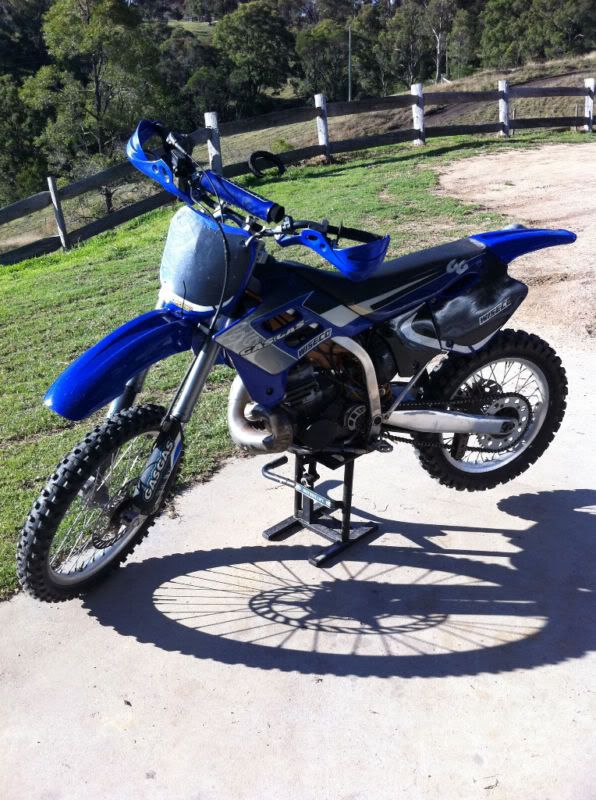
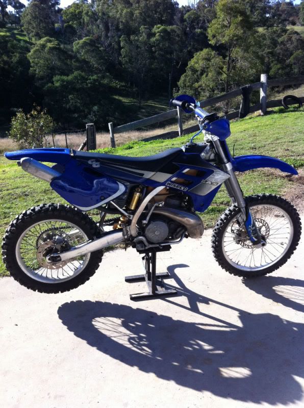
Here's a few pics from when I picked it up:


I wish to re-set it up as per factory with headlights, brakes, indicators so i can road register it for bush riding purposes..
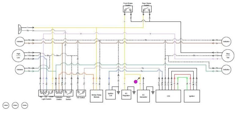
I have done lots of searching over this forum and found lots of informations, and guided by this information and my own electrical knowledge (pretty good i would say) I have managed to fully re-wire the bike as per my below diagram..

Now here is my issue.. When I measure the AC voltage coming from the generator on both the Low power (Yellow) and high power (White) to ground i get varying voltages from 10vac (cold idle) to 40vac (warm revving), but as soon as I connect either of these wires to the bike loom main power feed my voltage goes to 0vac and none of the lights or anything work but the bike runs fine..
I have fed a 12VAC power source into the system at the point marked on the wiring diagram with a Pink circled 1 and the chassis and all the lights work as they should so i am confident with my wiring..
I have measured the resistance of the lighting coil/generator and it seems to be within the spec of the service manual i have..
Basically pulling my hair out now trying to think of something that it could be but yer I am hoping someone has some ideas on what could be causing my lack of lights?
Cheers,
Nik
First up this is my first post of this forums so please take it easy on me..
I am in Australia.. I have recently (2 months ago) purchased a 2002 GG EC250.. Bike is fantastic and rides really well but had been electrically stripped down to the basics for racing purposes by the previous owner..
Here's a few pics from when I picked it up:


I wish to re-set it up as per factory with headlights, brakes, indicators so i can road register it for bush riding purposes..
I have done lots of searching over this forum and found lots of informations, and guided by this information and my own electrical knowledge (pretty good i would say) I have managed to fully re-wire the bike as per my below diagram..

Now here is my issue.. When I measure the AC voltage coming from the generator on both the Low power (Yellow) and high power (White) to ground i get varying voltages from 10vac (cold idle) to 40vac (warm revving), but as soon as I connect either of these wires to the bike loom main power feed my voltage goes to 0vac and none of the lights or anything work but the bike runs fine..
I have fed a 12VAC power source into the system at the point marked on the wiring diagram with a Pink circled 1 and the chassis and all the lights work as they should so i am confident with my wiring..
I have measured the resistance of the lighting coil/generator and it seems to be within the spec of the service manual i have..
Basically pulling my hair out now trying to think of something that it could be but yer I am hoping someone has some ideas on what could be causing my lack of lights?
Cheers,
Nik
Last edited:

