talk to me about rectifier/regulators

savage sausage

New member
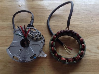
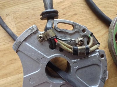
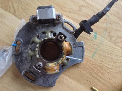
Ok so my bike has the cdi lighting stator (35w) and also the ducati external lighting coil which i beleive is rated upto 200w

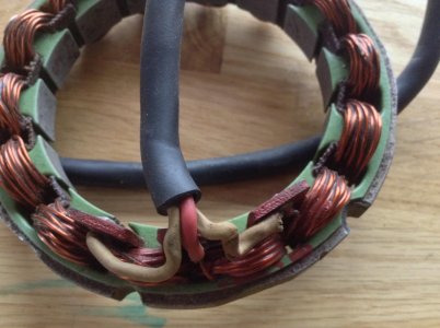
So I plan to use external lighting coil and im aware that I can 'float' the ground on this as it has 3 wires 2 yellows (+) and 1 red (-)
realistically speaking I plan to run a 35/55w HID bulb in the headlight, but which R/R do I need?? one to match the output of the stator or will a 100w one be ok.

I also want to run a capacitor instead of a battery

I've seen high power/output ones upto 200w watts for around 70 good ol english pounds,but I really dont want to be spending that amount,even trailtechs are expensive after shipping and import shafting tax

So any help would be appreciated
 

Attachments

  • IMG_0634.jpg
    IMG_0634.jpg
    117.8 KB · Views: 31
  • IMG_0635.jpg
    IMG_0635.jpg
    121.9 KB · Views: 29
  • IMG_0637.jpg
    IMG_0637.jpg
    122.1 KB · Views: 29
  • IMG_0636.jpg
    IMG_0636.jpg
    116 KB · Views: 29
Last edited:
ok so im just reading this sorry for not using search instead of starting a new thread,however this is good for newer models but it doesnt have the answers im specifically asking about the ducati energia generator.

2 yellows 1 red......so do I connect both yellows and red , 1 red 1 yellow ,2 yellow no red.:mad:

I appreciate not a lot of people have experience with older GG.
 
No experience with the older GG, but I agree with only using the external stator for lighting. That way only the ignition windings on the small stator are used (connected to the CDI, the pickup trigger also connects to the CDI).

Floating (isolating the ground) makes it easy to wire up. The real question is how the external windings are wound. It looks like the red wire is at the center point of the windings. Yellow to yellow would have full windings in the circuit and probably deliver too much voltage.

Red would typically be grounded, so you would have two outputs (X voltage from the first yellow to ground and Y voltage from the second yellow to ground).

An aftermarket rectitier/regulator typically has two blue wires for AC input and two wires (red and black) for DC output. In a floating configuration your external stator red wire would connect to one of the rectifier blue wires.

One of the external stator yellow wires would connect to the other blue wire. The rectifier ouput red and black wires would feed your DC lighting through a switch. Neither red nor black would be grounded. This is the safest way to try it.

My description is based on the GG300 quad wiring diagram which also used the external stator. See the attached file and look at the G symbol at the bottom center of the page. See how the red wire goes to a ground point and only one winding is connected (yellow wire). The G symbol to the right represents the how the ignition side of things is handled.

You should be fine with a 100W rectifier/regulator.
 

Attachments

Back
Top