You are using an out of date browser. It may not display this or other websites correctly.
You should upgrade or use an alternative browser.
You should upgrade or use an alternative browser.
2007 EC 300 Speedo
- Thread starter super_rat
- Start date
Speedo pics
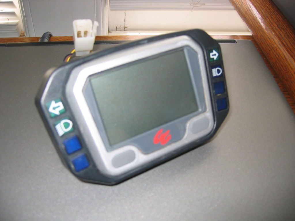
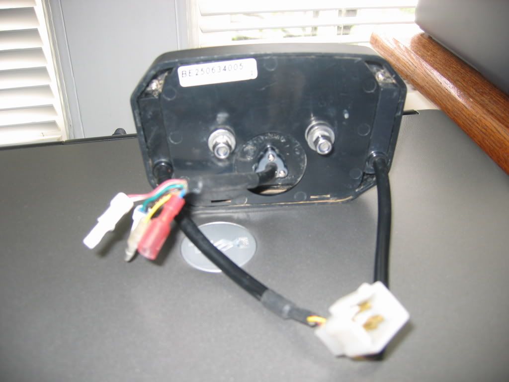
I don't know who makes it. Here are pics of front and back. A label with "BE250634005" is on the back. "Made in Taiwan", "10R-022812" and E13 are cast into the plastic on the back.
If this is the Trialtech speedo, where does the battery go?
Any ideas where to find a manual?
I don't know who makes it. Here are pics of front and back. A label with "BE250634005" is on the back. "Made in Taiwan", "10R-022812" and E13 are cast into the plastic on the back.


If this is the Trialtech speedo, where does the battery go?
Any ideas where to find a manual?
Speed manufacturer
Found it. Googling 10R-022812 took me here. http://www.acewell-meter.com/images/V1manual.pdf
Manual is at: http://www.acewell-meter.com/images/V1manual.pdf
It's an Acewell ACE 39xx computer
Seems to run on 12VDC.
Anybody have a document that describes the inputs? Nothing in the "manual".
Found it. Googling 10R-022812 took me here. http://www.acewell-meter.com/images/V1manual.pdf
Manual is at: http://www.acewell-meter.com/images/V1manual.pdf
It's an Acewell ACE 39xx computer
Seems to run on 12VDC.
Anybody have a document that describes the inputs? Nothing in the "manual".
Last edited:
armyoforange
New member
the red&white wire is for power i have mine hoocked up to a 9 volt battery i had it hoocked up to the ignition but it surged like your headlight does i have the 30 watt ignition or 2k2 i think the green and black wire is for your speedometer you should have gotten a 4or 5 foot leed that threades into your front brake caliper bottom and a pickup attatched to your hub the yellow wire is for your tack it ataches to the coil where the spark plug wire boot comes out of cant remember whitch one once i got every thing else runing i just touched the wire to the diferent conections until it worker sorrey for the bad spelling done didnt finish high school hope this helps ihad to do the same with my bike figure it out
Ud_luz
Member
Would you email it to: deltron@swbell.netVictory!! I got a PDF file from ACEWELL that shows the connections for the 2007 GG speedo. Let me know if anyone needs it.
Thanks, Bill.
Speedo now working
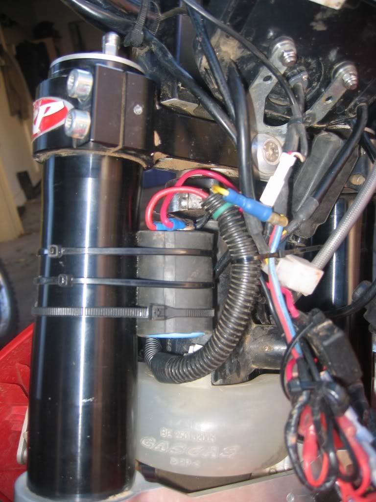
Finally got the GG/Acewell speedo set up. The Acewell pinout document shows that it had to run on DC so I had to get 12v DC on the bike. Bought a TrailTech rectifier/voltage regular (7003-RR150 ) and capacitor (040-CAP56) and a 10 amp fuse. By the way, if I were doing this again I'd get the smaller capacitor (040-CAP27). The CAP56 is HUGE. I got AC from the white coil wire I found taped up in front of the tank. The yellow lighting coil wire that would run the lights (if it had them) on the bike was left untouched. Everything works great. The capacitor even runs the speedo for about 5 minutes after shut down, letting you do set up with the engine off. The Acewell requires an external 9v battery for the clock so I also wired that up.
The speedo provides MPH, RPM, trip 1 odometer, trip 2 odometer, odometer, max RPM, max MPH, average MPH, clock, total time, run time, shift light.
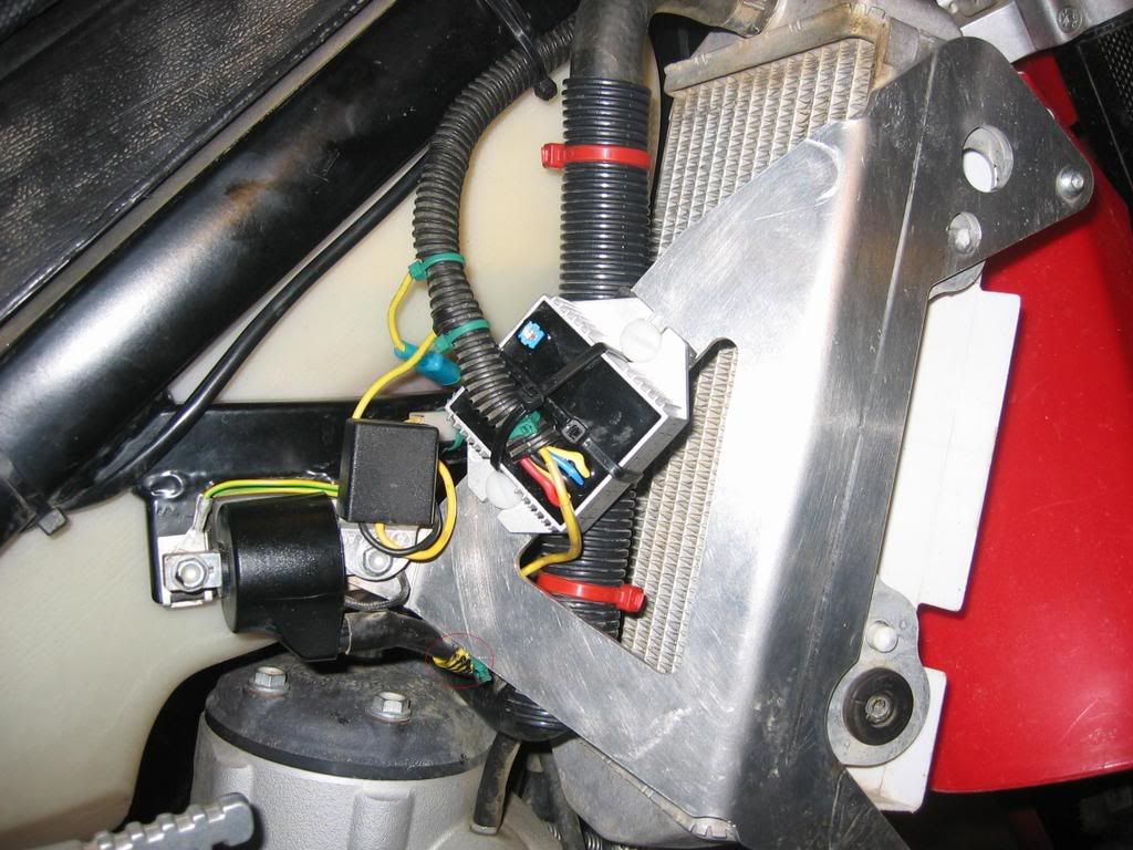
Mounted on rubber with nylon bolts. Red circle is tach pickup.
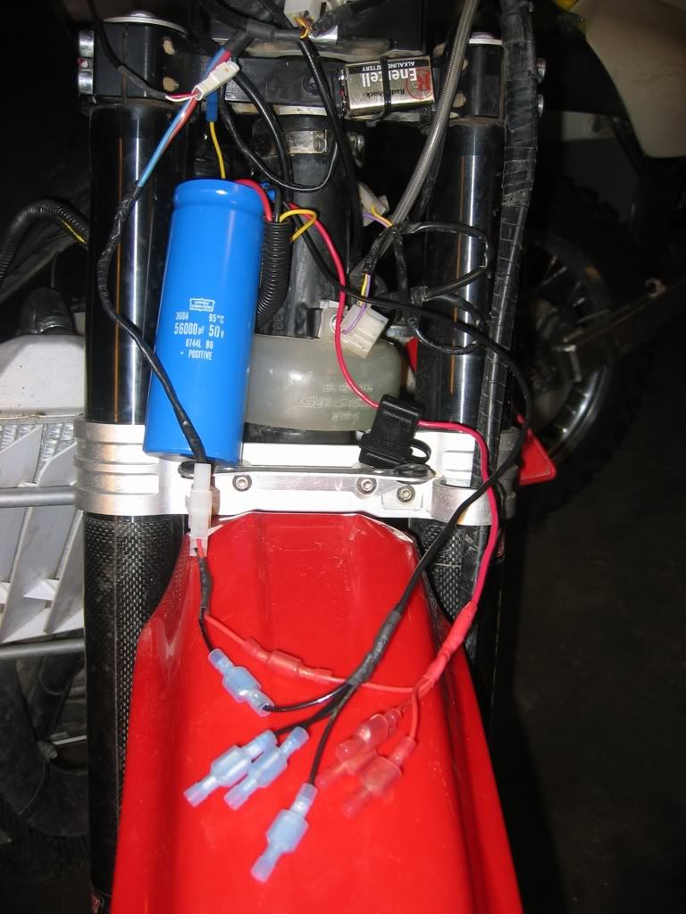
Made a wire loom with 4 positive and 4 negative terminals. May want to run a GPS.
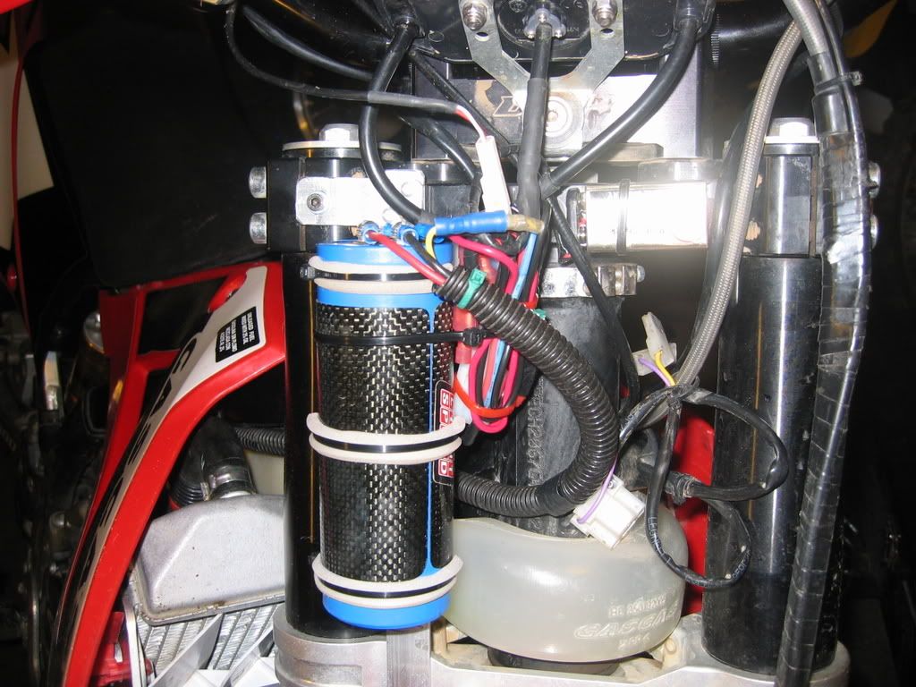
Finished install. Note 9v battery upper right.
Finally got the GG/Acewell speedo set up. The Acewell pinout document shows that it had to run on DC so I had to get 12v DC on the bike. Bought a TrailTech rectifier/voltage regular (7003-RR150 ) and capacitor (040-CAP56) and a 10 amp fuse. By the way, if I were doing this again I'd get the smaller capacitor (040-CAP27). The CAP56 is HUGE. I got AC from the white coil wire I found taped up in front of the tank. The yellow lighting coil wire that would run the lights (if it had them) on the bike was left untouched. Everything works great. The capacitor even runs the speedo for about 5 minutes after shut down, letting you do set up with the engine off. The Acewell requires an external 9v battery for the clock so I also wired that up.
The speedo provides MPH, RPM, trip 1 odometer, trip 2 odometer, odometer, max RPM, max MPH, average MPH, clock, total time, run time, shift light.

Mounted on rubber with nylon bolts. Red circle is tach pickup.

Made a wire loom with 4 positive and 4 negative terminals. May want to run a GPS.

Finished install. Note 9v battery upper right.
slocalspode
Member
Super Rat wrote:
"Victory!! I got a PDF file from ACEWELL that shows the connections for the
2007 GG speedo. Let me know if anyone needs it."
----------
I would be very interested to get a copy of the .pdf showing the connections
for the Acewell computer. I went to their web site and only found the users
manual. Nothing showing the color coding or what connectors feed what
information to the computer.
I picked up a used "take off" from an 07 TXT and it is missing the tach and
temp sensor wire connectors.
That and I don't know which wire to feed it 12VDC to get the clock and
LCD back lighting to work.
I would appreciate it very much if you could send it by PM here or send
it to my earthlink acct. jjwallace@earthlink.net it will bounce with a spam
message because you are not in my address book. Ignore the warning.
Thank you, Jeff So-Cal.
Good god man that capacitor is HUGE! Who told you to use that? It probably holds enough current to do some arc welding ! Looks like something from a 1960 tv set. I'm sure something the size of the tip of your finger would have worked, plus I don't think you needed DC, although it would be nice for the gps power.
The same unit works on my 2006 and don't think there is any dc in the system. I'll have to hook up the 9V battery though so the clock doesn't reset every time.
The same unit works on my 2006 and don't think there is any dc in the system. I'll have to hook up the 9V battery though so the clock doesn't reset every time.
slocalspode
Member
Super Rat:
Where did you hook up the ground wire from your 9V battery?
My Acewell only has a yellow wire exiting from the center wire
bundle, along with the three tiny connectors. I assume these
are for 1) speedo, 2) RPM, 3) water temp.
I tried touching the (+) of a 9v battery to the yellow wire and
grounding the (-) to the mounting bracket. No go...
I can get a close up picture of the back side wiring sometime
this weekend for a comparison.
Thanks, Jeff in so.Cal.
slocalspode
Member
I found this with a google search. Acewell wiring diagram.
http://s3performance.com.au/download/Acewel3967wiring_diagram.pdf
this may be the solution to my delima.
Is it the same .pdf file that Super Rat was eluding too?
Jeff So.Cal.
http://s3performance.com.au/download/Acewel3967wiring_diagram.pdf
this may be the solution to my delima.
Is it the same .pdf file that Super Rat was eluding too?
Jeff So.Cal.
mountain thumper
New member
is that an easier way to add juice than a dc stator? on the trail tech site it says dc stator sold seperately. i want to add some kind of capacitor to run blinkers, without going to a bigger stator. im a noob, so im not even sure if im looking at this right..
slocalspode
Member
Hmmmm... Now I am more confused than ever. After looking at Super Rats'
Acewell gage and comparing the one I have. They seem to be different
configurations of the same gage. The front of the gage looks the same.
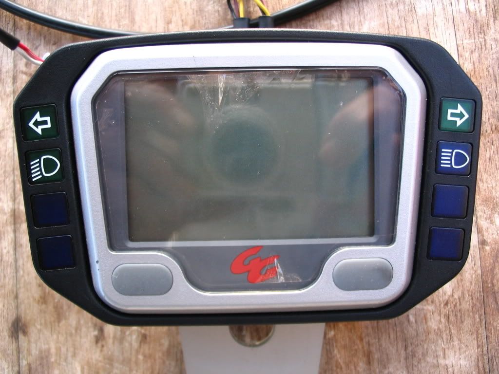
The back of the unit has a different part number, BT280634005. This one is from
a 2007 TXT trials bike.
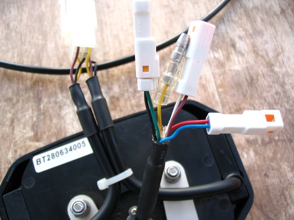
The wiring is different from the diagram(s) I've down loaded, and this is leaving me
perplexed.
As you can see from the picture. It has three connectors and one yellow wire
coming from the middle tap. The Green/Black is connected to the speed sensor
wire. And seems to match what the wiring diagram depicts. It is the other two
connectors that don't seem to match. I do not know what functions are
supposed to be hooked up to the Blue/Red and the White/Brown (or Purple)
wires. I assume these are for water temp....and ????? who knows. I doubt this
would be a fuel gage on a trials bike. According to the diagram the yellow
wire goes the the Coil or spark plug wire for RPM readings.
The outside wire bundles control the High/Low beam and turn signal displays
only.
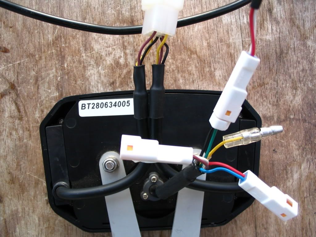
This consists of two black wires, (joined together @ one pin) and two each of
Yellow and Brown, or Purple wires.
So I guess what I am asking if if anyone can tell me what the two connectors
are for and which ones are for the clock function + and -.
I guess me next step would be to contact my local Trials dealer or
Dale Malasek, the GasGas importer.
Thanks for any information or suggestions you can provide.
Jeff So.Cal.
Acewell gage and comparing the one I have. They seem to be different
configurations of the same gage. The front of the gage looks the same.

The back of the unit has a different part number, BT280634005. This one is from
a 2007 TXT trials bike.

The wiring is different from the diagram(s) I've down loaded, and this is leaving me
perplexed.
As you can see from the picture. It has three connectors and one yellow wire
coming from the middle tap. The Green/Black is connected to the speed sensor
wire. And seems to match what the wiring diagram depicts. It is the other two
connectors that don't seem to match. I do not know what functions are
supposed to be hooked up to the Blue/Red and the White/Brown (or Purple)
wires. I assume these are for water temp....and ????? who knows. I doubt this
would be a fuel gage on a trials bike. According to the diagram the yellow
wire goes the the Coil or spark plug wire for RPM readings.
The outside wire bundles control the High/Low beam and turn signal displays
only.

This consists of two black wires, (joined together @ one pin) and two each of
Yellow and Brown, or Purple wires.
So I guess what I am asking if if anyone can tell me what the two connectors
are for and which ones are for the clock function + and -.
I guess me next step would be to contact my local Trials dealer or
Dale Malasek, the GasGas importer.
Thanks for any information or suggestions you can provide.
Jeff So.Cal.
DC power
Mountain Thumper - you don't need a DC stator if you do what I described. Yes, what I did is much easier than replacing/modifying the stator. What I did will run lights and blinkers also, although you can still run lights on the existing A/C circuit.
slocalspode - the red and blue goes to DC power (red is positive, blue negative). The white and brown wires go to a 9vdc battery (white is ground) that runs the clock. The yellow wire with the bullet connector is the tach pickup. The wiring on yours looks just like mine.
super_rat
slocalspode
Member
Thank you for responding to my questions.
Let me see if I got this straight.
The red/blue needs 12VDC from the rectifier and
the white/brown needs 9VDC?!?!
Two power sources....hmmmm... I assume one to
keep the clock functioning and the other to power
the gage and LCD backlighting.
These are unique style connectors, (to me anyway).
I think I need to make a call to ElectroSport and see
if I can purchase some of these from their accessory
catalog. They make a 9V battery holder with the proper
connector, I believe.
Thank you for your help.
Jeff So. Cal.
ec 300 SPEEDO
Yep, you have it correct. 9 vdc keeps the clock going.
I used a 9v transistor battery. Radio Shack sells the battery connector and bracket to hold it.
I cut off all the speedo connectors (except for the speedo pickup), soldered on more wire length and then used "normal" connectors to hook everything up.
ec 300 speedo
cdn280 - I thought an arc welder on the trail would be pretty handy - you know trail repairs, etc.
Seriously, I was looking for something around 5,000 uf and didn't read the TrailTech description very well. It is 56,000 uf, about 10x more than I needed.
I'll probably replace it at some point. Didn't cost that much.
super_rat
slocalspode
Member
Looking a little closer @ the wiring diagram, I think the light in
my head is starting to flicker.
The Brown/Black keeps the clock running and the Blue/Red
is a switched, (on/off) function to turn on the unit.
I am assuming, (there I go again), that you could run the
whole unit on the 9V battery and install a switch on the
handle bar to turn in on/off. Otherwise I'd need to install
a rectifier, like you did, to provide DC power. I have a small
rectifier that came off my EC300 that was used to provide
DC to power the horn. It should be more than strong enough
to power the gage alone. I installed the same TrailTech
Rectifier/Regulator that you did after doing the floating ground
modification mentioned in another thread. Now my 300's system
is fully DC and runs a small 1.2Ah sealed lead/acid battery.
I am planning on using this AceWell on another bike some time
in the future.
Thank you again for your help, it is much appreciated.
Jeff, So.Cal.
Similar threads
- Replies
- 6
- Views
- 1K
- Replies
- 2
- Views
- 742
- Replies
- 0
- Views
- 289
- Replies
- 4
- Views
- 193

