2013 EC250 blowing voltage regulators

rubber Jonny

New member
Hi all,

My 2013 ec250 has about 70 hours on it now and in this time its blown 2 voltage regulators one at 40 and now at 70 hours. The headlight bulb totally shatters when the regulator goes.

Does anyone have any ideas/on why this could be happening? Surely this is more than bad luck? Once maybe but not twice........

Cheers, RJ.
 
I would start by checking the output from the stator at both idle and while being revved.
 
That sounds about right. My measurements showed 15.4 VDC max at the battery. I would be concerned if it went over 16V.

I would suspect a bad connection somewhere or possibly the mounting/grounding of the case. On my 2011, the voltage reg/rect bolts to the aluminum subframe. This dissipates heat well, although I don't think these units warm up all that much. I know a 3 phase reg/rect will run much warmer (street bike or some dualsports).

Trace the green/yellow ground wire on the reg/rect and see if it has a good connection to frame ground. Note that some wires joints are hidden in the sheathing and are hard to get at.

Definitely trace the wires from the stator to the reg/rect. Remember that the reg/rect basically shunts excess voltage. If your yellow wire (AC lighting) did not connect well to the reg/rect the excess voltage would not be clipped and then the over-voltage would take out the lights.

This raises the question: How do you know it's really the reg/rect that fails? Maybe it's time to cut one of the old cases open to see if a diode is melted. Changing out the unit might have moved the wiring enough to re-establish a connection.
 
I'm not convinced it would take 30 hours for a bad connection to show up, but I've seen some strange things. I once had a section of wire that looked and felt perfectly good, but the copper inside was corroded through. Likely a defect in the copper.
 
When i got this bike it had done 30 hours, the regulator blew at 36, gas gas gave me a new one free of charge as the bike was 5 months old. Now its over the 6 month warranty so its not covered and has done 70 hours. I ordered a trail tech adjustable regulator (ac only no battery / starter etc) as people seem to consider these a upgrade, more reliable and the same price. I have had the flywheel off and its perfectly clean in there looks fine, no discoloring dirt etc.

Its arrived today so hopefully i will get time to fit it and see what happens.
 
Stolen from the internet:
Continuous-preservation (float) charging: 13.4 V for gelled electrolyte; 13.5 V for AGM (absorbed glass mat) and 13.8 V for flooded cells
All voltages are at 20 ?C (68 ?F), and must be adjusted -0.022V/?C for temperature changes.
Float voltage recommendations vary, according to the manufacturer's recommendation.
Precise float voltage (?0.05 V) is critical to longevity; insufficient voltage (causes sulfation) which is almost as detrimental as excessive voltage (causing corrosion and electrolyte loss)
Typical (daily) charging: 14.2 V to 14.5 V (depending on manufacturer's recommendation)
Equalization charging (for flooded lead acids): 15 V for no more than 2 hours. Battery temperature must be monitored.
Gassing threshold: 14.4 V

We can say 13.5V for storage charging and approximately 14.4V for daily operation. So yes 16V is high. I only use LEDS lights on my bike, maybe the 15.4V maximum I've seen is being handled OK by my electronics.

If your voltage never goes over 16V, it sounds like your regulator is working. Your windings probably output 60V at maximum RPM. The 16V will definitely shorten bulb life, but I would expect the bulb to still last multiple hours.

It may be that a battery equipped bike holds the voltage level lower because of the presence of the battery. I suggest you try loading the system with more wattage to see if that pulls the voltage down. Try using a 100 watt headlight bulb.

No one else has posted about bulb blowing that I can remember. There must be something odd about your bike.
 
Googling "16V headlight bulb" brings up lots of choices, so manufacturers must expect bulbs to function at that voltage.
 
I ordered a trail tech adjustable regulator (ac only no battery / starter etc)

As far as I know Trailtech only supplies a fullwave rectifier. Did they say to use it on a non-floating electrical system? It might only function as halfwave in this case (which would match what the stock unit does).
 
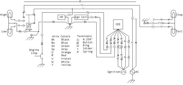
One thought: Are you sure the stator YELLOW wire is connected to the voltage regulator? If it was wired wrong and the white wire was connected, you might get a higher voltage.

Look at the simplified GASGAS wiring diagram: Only the yellow wire from the stator is connected to the regulator. On the diagram, the stator is the circle with the AC wave symbol, located in the lower right corner.

A wiring mix up would make sense since it is an ongoing problem.
 

Attachments

  • gg-wiring.jpg
    gg-wiring.jpg
    26.8 KB · Views: 48
Hi Neil, thanks for the in depth replies, much appreciated.

Some answers to these questions,

I have that wiring diagram, followed all the colours / connectors and it seems ok, no wrong connections. Got my mate to look over it too, he couldnt see a problem.

I tried a 100w bulb, popped it straight away.

Yes it is the yellow wire connected not the white.

I agree the regulator must be working just not properly. When the regulator blew it put out 30+ volts at the headlight and totally shattered the headlight bulb as if i had hit the glass with a hammer.

I have tried a known good gas gas regulator on my bike it acts in a similar way to the trail tech, 12v at idle, upto 16v when revved.

The regulator I have is the one at the bottom of this link.

http://www.trailtechproducts.co.uk/acatalog/Regulator_Rectifier.html

Trail Tech AC Voltage Regulator
- Improved AC Regulator with Adjustable Output.
- Universal voltage regulator limits voltage to 12.0-16.0 volts for AC systems (DC systems require a regulator/rectifier.)
- Conditions circuit to eliminate electrical spikes, protect from lamp blow-outs, and reduce flicker and dimming.
- Dial-a-Brightness for halogen and quartz lights:
- At 14+ VAC setting, the lamps will approach HID lumens (~70%) but lamp life is short (good for racing.) ~25 hour lamp life.
- At standard setting, about 13.8 VAC, the lamps should last about 500 hours.
- At minimum setting, the lamps are not as bright as HID (~30%), but last over 1,000 hours.
Included in Trail Tech plug-and-play high-output AC electrical systems with model-specific connectors; no cutting or splicing required.
Designed and manufactured by Trail Tech.
 
I think i am going to make a new test loom for the light to rule out any bad connections on the standard loom like in the link below using a spare bulb holder I have. At least this way it could rule out all the wiring, switches etc. Its only a few spade connectors so will only take a few mins. Only connection to the bike will be the yellow coming from stator earth it elsewhere.

http://www.electrosport.com/technic.../electrosport-esr012-fitting-instructions.pdf
 
Part Number: 7003-AC01 is the one I would choose too. I assume you've tried the pot at it's minimum setting?

Did you measure voltage without the light bulb and regulator, engine rev'd? I'm just curious to see what the non regulated voltage is. The results you are getting sounds like somehow the headlight bulb is NOT in the regulated circuit, although it must be if your measurement does not exceed 16V.

So now how are you measuring the stator output? Remember that this whole scenario will be AC voltage. A DVM (digital voltmeter) may not respond fast enough to show you a peak voltage. You may be reading an averaged value, but the peak is what's blowing the bulbs.

Any chance you've got an electronics buddy with a recording type hand held digital oscilloscope? Then you'd see what the regulator is doing. It should look like a series of humps with flat tops. The flat tops would be at the 16V limit. Turning the pot down should move the flats lower to 12V. The tricky part is that the frequency of the waveform is changing proportional to RPM, so that's why "capturing" it is important. The frequency change alters the time base needed to "see" the waveform. That is why a standard meter won't be good enough to get real answers.

Your idea of a separate test method is spot-on. When in doubt go back to each part of the system.
 
Without a definite answer, the only thing I can think of is to mount a 14V zener diode on a plate of aluminum and connect it to the headlight wire. If you remember British bikes from the 60's, that was the finned thing under the triple clamp. The airstream provided cooling for the extra energy that the diode clipped when the lights weren't on.
 
Another experiment would be to get a 24V bulb from a military vehicle and see if it survives.

You might wind up being the guy with fantastic offroad lighting if your bike can power a 120VAC 500W halogen floodlight (sorry, couldn't resist).
 
I tried earthing the regulator to my bench, the regulator works properly like that. The standard earth point was perfectly clean, made a extra earth on a different part of the frame. Regulator works well like that too, a bit confused so will have to have a test ride check it over again.
 
A bad ground path will certainly cause problems. Paint / dirt / corrosion must be removed. If the regulator does not have a ground, the headlight will receive the full AC voltage that the stator is putting out.
 
@Neil E., It?s not always helpful to use colours for wires except the power and ground universal colouring scheme if your car?s electrical system has been repaired a lot. Many technicians don?t care a lot for the colouring schemes so they just place the wires they have in the workshop. It is much better to see which terminals these wires originate from to find out their possible sinks. For example, if a wire is originating from Pin 1 of a relay, it is much easier to find datasheet of that relay to find out what the purpose of that pin is. This enables us to reach the destination for that connection easily.
 
Back
Top