Kokusan Blues

I've been pondering the statement, "The CDIs do have different curves. They vary by year and displacement, some years the 250s and 300s having different curves" because of what iancp5 said:

"This is quite an interesting thread. I wonder if it accounts for the some GG's don't idle properly issue?"

The question is whether these differences are design differences or the result of variance in part tolerance for the ignition assembly.

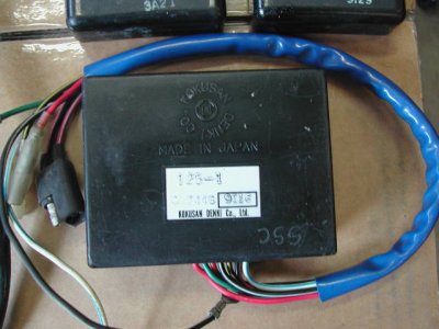
I just checked the GoFasters' parts fische, and it shows 2004 - 2007 250s and 300s having the same ignition CDI box. From a parts inventory standpoint (at least in the latter years), displacement and year don't seem to affect the part number (ME250534077). Actually, from that part number, the CDI box hasn't changed since the 2000 model year.

The 200 CDI box is the same part number, too, perhaps dispelling the difference in 200 vs. 250 vs. 300 CDI advance curves. I say "perhaps" because I am only speculating. I don't really know.

The other thought i had would be whether GG has enough time to do a "study" on the variance between CDIs. How do they get enough time to sample enough CDIs to determine whether variance in CDIs has much influence on engine performance? Given their size, they probably don't.

When visiting the factory, the engine pre-installation test cell has one CDI box for 2T engines and one CDI box and one FI box for 4T engines. They test engine performance against the standard ignition. They don't test the assembled system to measure the system performance. (They install the CD box on the assembly line).

Thus, they have data for the engine, but not the system. They don't run a chassis dyno at the end of the assembly line, so the system might be highly sensitive to production variance in the CDI. They might not know, just as we don't. It could be production differences in the CDI can account for significant performance differences in individual bikes.

OK. Just thinking out loud. Back to work.

blitz
 
Blitz, My friend who just bought the new CDI for his 300 found just what you did, that one unit is listed for all the models. I think that this is a recent development, more to do with what is currently available. This unit is also the one with the multi pin connector. Had I ordered this for my bike, I would have needed the multi pin connector that goes with it, and a bit of a pigtail with it. I don't see it available, guess I'm supposed to buy a wiring harness.


The shifter kart ignition I got on eBay was one of two the seller had, from a parts closeout he bought in a lot. He doesn't know where to get more. I would think that a kart shop might be able to look them up. They work great.


I just got my hands on a KTM Kokusan. This CDI has the multi pin plug, and comes with part of the wiring harness. The wiring is the same color code. It will be a piece of cake to hook up. I'm gonna go give it a try, I'll let you all know how it works, Buzzard
 
Some GG part #s are not quite right on the older bikes, or, perhaps the physical CDI boxes are considered the same part despite the differences in mapping. The two I had had identical part #s on the plastic case. In '01 or '02, they started to differentiate the CDIs with different color shrink wrap on the harness, with one color being black. Before that they were all black. There is also the possibility of them using what they have to get product out on time, that is a 250 CDI in a 300 for example.

As far as variance or production tolerance in CDIs causing performance differences, I doubt it, as its a digital device.
 
I've seen many instances of "digital devices" providing different performance levels. These aren't strictly "digital"; they're more hybrid in that pulse timing and the front end circuit can be "trimmed." There's an analog to digital conversion in the pulse signal. If the threshold for the pulse leading/trailing edge changes, i.e., the ADC changes, that can affect ignition timing.

Of course, there's the "absolute" measure of digital: It works or it doesn't!

Just a thought.

The other "variance" piece is the post which started this; Buzzard's buddy's timing was full advance, and then later retarded. it "worked," but it didn't "work." It produced spark, but at the wrong time. Something "failed" or wasn't quite right with that ignition, either. So, something led to a variation in performance. All components at the "bottom" end of acceptable tolerance? One piece out of tolerance?

Not trying to argue, but just better understand.

Thanks for all of the input. I am learning a great deal.

blitz
 
As far as variance or production tolerance in CDIs causing performance differences, I doubt it, as its a digital device.

I've seen many instances of "digital devices" providing different performance levels.

I have to agree with blitz, a CDI has analog components, the output -when the spark is there- relies on the spark coil impedance+capacitor charge+capacitor internal impedance+thristor timing and so on, but the output tolerance is almost negligible compared to the input, among others you have the following "analog/mechanical" tolerances.

-Stator position.
-pickup magnet position
-pickup coil position
-pickup coil distance to magnet
-electronic trigger point at the pickup input.

Of course, all the above can be easily fixed using an stroboscopic gun and measuring the TDC.

GDM, I don't want to hijack this thread, but what do you think about a CDI that is able to keep the engine at idle??. Do you think is it worth to try a CDI that smoothly changes the advance when the engine is below a certain rpm (let's say 1200 or 1500 rpm??). If so, I will design such a CDI, starting with a kind of "CDI recorder system", just to know how my current CDI is working, this will allow me to test power supply, shielding, input sensor schmitt trigger and so on.

have fun,

j.
 
Well, I mounted up the KTM Kokusan to my GasGas. It fired right up and idled. I roared out of the driveway, and down the street. Strong low end, some middle, no top. I putt back to the garage, pull the cover, and put the timing light on it. It starts at maybe ten degrees advance (now this is at an idle, ten degrees beyond the static setting), and decreases to no advance as RPM increases. I bought this KTM CDI on eBay, complete with coil, kill button, and wiring harness, for $42. Some chopper shop was parting the bike out. 2005 250EXC. Some former KTM owner probably had a terrible time trying to jet his bike, and was then glad someone finally heisted it, to end up on eBay. (That last comment was tongue in cheek, by the way.)


So, I'm going to go way out on a limb and say, this KTM Kokusan is trash, another bad ignition. KTMs are not immune from bad Kokusan CDIs. You can look at these black boxes until your head hurts, but you won't know what they are really doing until you put a timing light on it.


What I did get for my money was 1) some more education, 2) I think that the multi pin plug just might be the same as the newer GasGas CDIs use, so if I get my hands on a newer unit, I can install it, 3) a really nice kill button and coil. I'll keep on looking into this, keeping my eyes open for new things to try. Buzzard
 
Yes there will be some analog components but I think what your describing is more like an old style analog CDI. Huskys still use these with a Kokusan stator. We won't really know what is inside the box for sure until someone leaks a schematic.

What I mean is the mircocontroller, whatever it is, is not going to run different with the same code, and if the CDI passes QC at the factory, it should perform without any big variations. I'm not talking about failure just tolerances. Sure, an internal component could fail and perhaps cause the uC to sense a false condition, but at this point is just speculation. Yes, I agree the external stuff is the biggest variable.

What I would do first is set up a test fixture and software on a PC to analyze the existing CDI(s)in detail, independent of the bike. As an alternative you could use a scope and a function generator. Then you have a baseline for your own map. Someone should try and determine or find out what the power requirements(from the stator coil) are, so this can be emulated on the bench.

You guys are going to get me worked up about this when I don't have the time.:mad: ;)

I think we are making many assumptions.
It is very "unlikely" that the digital bit has been mis-programmed but not impossible. After all most data loading systems have a verify step so the chance of some random numbers getting in is small at this stage.

But! The micro may be programmed correctly with the wrong program. I.e. it has no fault, the human who loaded the map for that batch screwed up or GG gave them the wrong map etc. Also we assume that there are sufficient automated checks that the code loaded correctly. What if load to the production line programmer failed halfway through would they spot it or do they assume it's so unlikely no one checks? In this case maybe you get the default unprogrammed advance for an empty map. I mean do they pay the guy enough to have one who understands why when it says verify y/n pressing y is a good thing even though it takes longer? I've worked in factories and some workers only do things if not doing them means a loss of salary. They don't think about what is right, wrong, good or bad.

Are there analog inputs to the micro as well as outputs?

I can't believe GG doesn't change the map yearly. Surely they make minor changes to engine and then get on the dyno and test track to harmonise the system? Therefore is the part no. for the hardware only and is not related to the code inside. Any other manufacturer I would say impossible but GG ................... Let's be honest great designs but the quality control aint great.

Or maybe all 2 strokes enduros require the same curve and Kokusan just make one CDI - surely not? :eek:
 
Your really stretching on this one. It just doesn't work that way, you can't half flash something wrong. Its called a checksum, where the sum of the code has to equal a certain number to assure a correct download or programming operation. These come from Japan, and are likely flashed to spec in numbers, and go through rigid QC. How they are handled at the GG factory, or what the importer in a particular country may do is anyone's guess.
 
It is a stretch, but it isn't inconceivable that someone made changes to the uC code, it compiled, but the code was wrong. (Remember the satellite where the unit conversion from miles to KM was wrong, and the satellite missed its target by miles (pun intended)?) This could be a sign error or something like that in the timing map.

Maybe kokusan flashed a bad batch of CDIs, and their QC process didn't catch it. Stranger things have happened. Maybe the map retards at overrev, but the map is wrong 'casue the break point is in the wrong "spot." An incorrect map would still compile. If it compiles, it would look "right." It's a stretch, but it has happened.

Also curious is the advance/retard behavior that Buzzard saw with both CDIs. Maybe this points to a bad pulse sensor which has an out of spec inductor increasing the time constant of the pulse pick up. If LR is too high, the sensor could alias at high speed, causing the apparent retardation in the ignition timing. Maybe the problem is pointing to the pulse pick-up rather than the CDI box itself.

Buzzard, can you swap pick ups? Might be a long shot, but worth a try. On second thought, did someone check the resistance on that sensor, or was that another thread?

Again, thinking out loud. Thanks for keeping this alive. It's not so much fun for Buzzard as his bike doesn't run right, but fun to try and figure it out.

blitz
 
I'm going to try attaching some pictures of the cast of players.
 

Attachments

  • December 08 Arizona MG GG 038.jpg
    December 08 Arizona MG GG 038.jpg
    52.1 KB · Views: 60
  • December 08 Arizona MG GG 039.jpg
    December 08 Arizona MG GG 039.jpg
    57.1 KB · Views: 56
  • December 08 Arizona MG GG 040.jpg
    December 08 Arizona MG GG 040.jpg
    56.6 KB · Views: 61
  • December 08 Arizona MG GG 041.jpg
    December 08 Arizona MG GG 041.jpg
    60.3 KB · Views: 75
Hey, that worked. My bad GG CDI, black sleeve, good GG CDI, red sleeve, KTM CDI, shifter kart CDI, and my 2K2 ignition. To answer a few questions, I also have a 2K3 ignition. It is presently on the bike, with another kart CDI unit. The 2K3 is brand new, including pickup sensor. Both ignitions gave the same results with the various CDIs.


I would like to thank the site member who goes by the name RichardCranium. I purchased the good GG CDI, 2K3 ignition, and a couple of other things from him. He's great to deal with.


I'm going to blather on a bit about these pickup sensors. Notice the metal strip on the flywheel, it's raised a bit. The pickup sensor is a magnet with a coil of wire around it. When this strip of metal passes through the magnets field, a current is produced in the coil. At the moment the tail end of the strip clears the magnet (the center of the pickup), the field collapses. This field collapse is what triggers the CDI. So, one can somewhat accurately time a CDI equipped bike statically by using this point on the rotor lining up with the center of the pickup. The piston/crank need to be at 1mm BTDC (or wherever you wish to set your timing) when the tail end of this strip is at the center of the pickup. In my experiences with a timing light, this does indeed work out.
 
By the way, if any of you want to tear apart and anayze any of these bad ignitions, let me know. I can get them to you.


I would like to hear from someone from Kokusan, to tell me, and all of us, what is happening here. I wonder right now if these units were bad when new, or did a semi-conductor fail? Was moisture intrusion possible? Did a UFO get too close to these units? What happened? Buzzard
 
Buzzard,

Glad the bike is running.

I have one i have taken 1/2 way apart, but then i got busy, and never fully took it apart. If no one else calls them, I wouldn't mind taking the old stuff. But, i might not ever get to it, so if someone wants it, they'd trump me.

I know that Glenn is itching for another project, so he might call it, too.

I am glad your bike is back to normal.

blitz
 
stator plate timing

Bringing this old thread back to life. The bump on the flywheel triggers the CDI discharge and the flywheel is keyed to the crank. Some folks have commented that turning the stator plate changes the timing. How does turning the stator plate make the timing change?
 
Well that was a rather silly question to ask. The trigger unit is bolted to the backing plate, so when the plate rotates the timing changes. The trigger point is altered relative to the crank location.

At a quick glance with all the parts mounted in the engine, the trigger unit on a 2K3 looks to be attached to the engine case, but it's not.

Correct. If you turn the stator Clockwise you will advance your timing. If you turn it counter clockwise you will retard your timing.

Timing is a funny thing. You want the most amount of timing you can get at a lower RPM with out detonation for a strong bottom end and then retard for High Rpm's for good top end. Our Pro stock 1000cc Arctic cat drag snowmobile running on 114 octane race fuel turning 9300 Rpm's has 32* BTDC of timing at 3000 Rpm's but only 13* BTDC of timing at 9300 Rpm's. We have advanced the engine to 40* BTDC at low RPM but the engine started and ran backwards.:eek:

My Old Yamaha IT200 had no timing curve at all. It started and stayed at 20* BTDC. That worked great for low Rpm's but left a lot on the table for top end.
 
Back
Top