2011 EC 300 Pre Race Season Rebuild

Moto7man

Member
While the parts supply is still good, I decided to check some things on the gasser because I'm going to hang on to it even though I'm going to buy another brand for 2016. The bike only has about 150 hrs. Please feel free to comment on any of the procedures or parts.

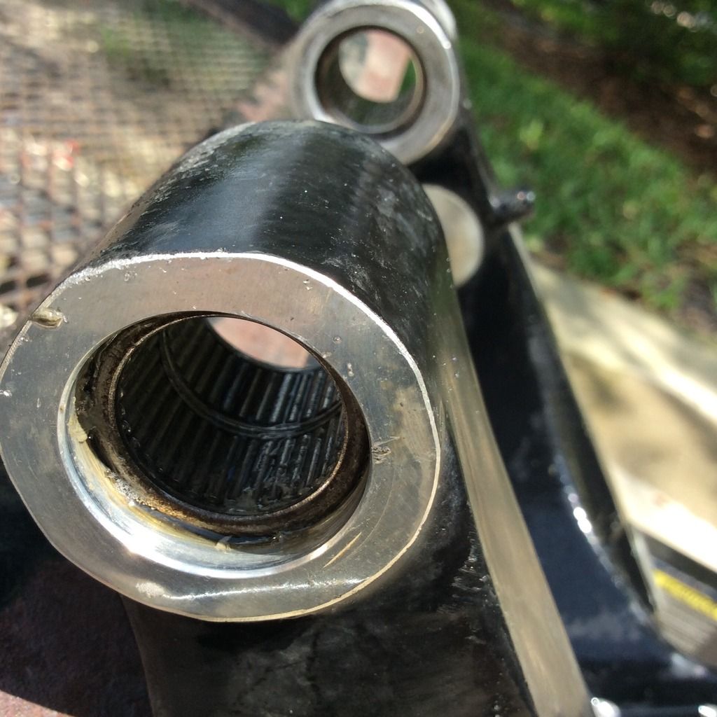
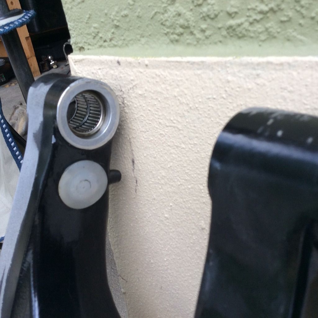
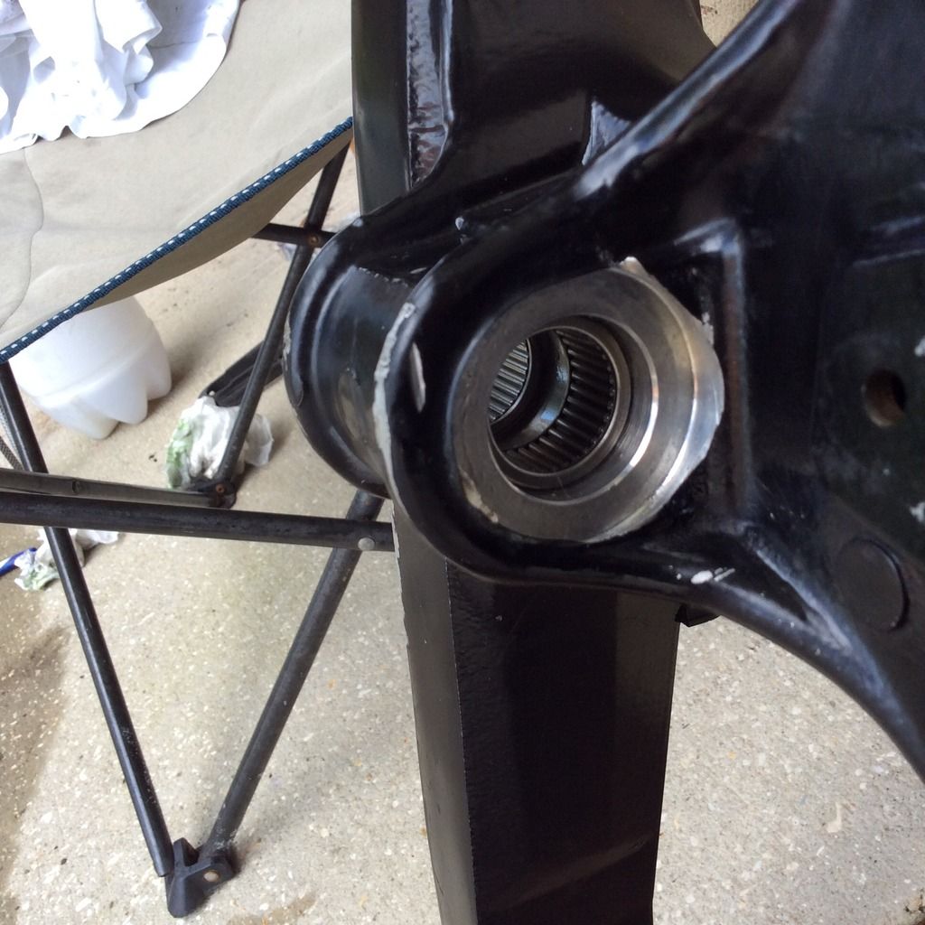
First, I did the swingarm bearings and suspension link bearings. I was surprised that the the swingarm bearings had a lot of crap in them. However, when they cleaned up fine. I pulled all the pins out, cleaned everything up then repacked them with salt water proof grease. Be careful not to lose any pins in the disassembly. The bushings didn't look too great so I replaced them.

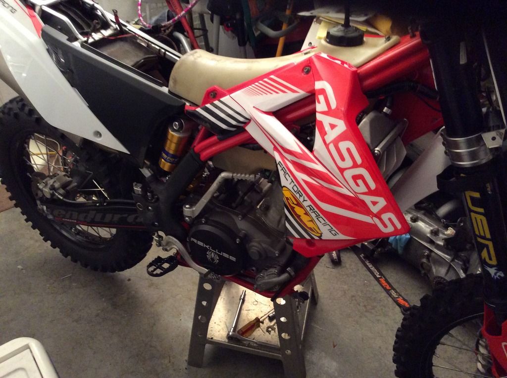
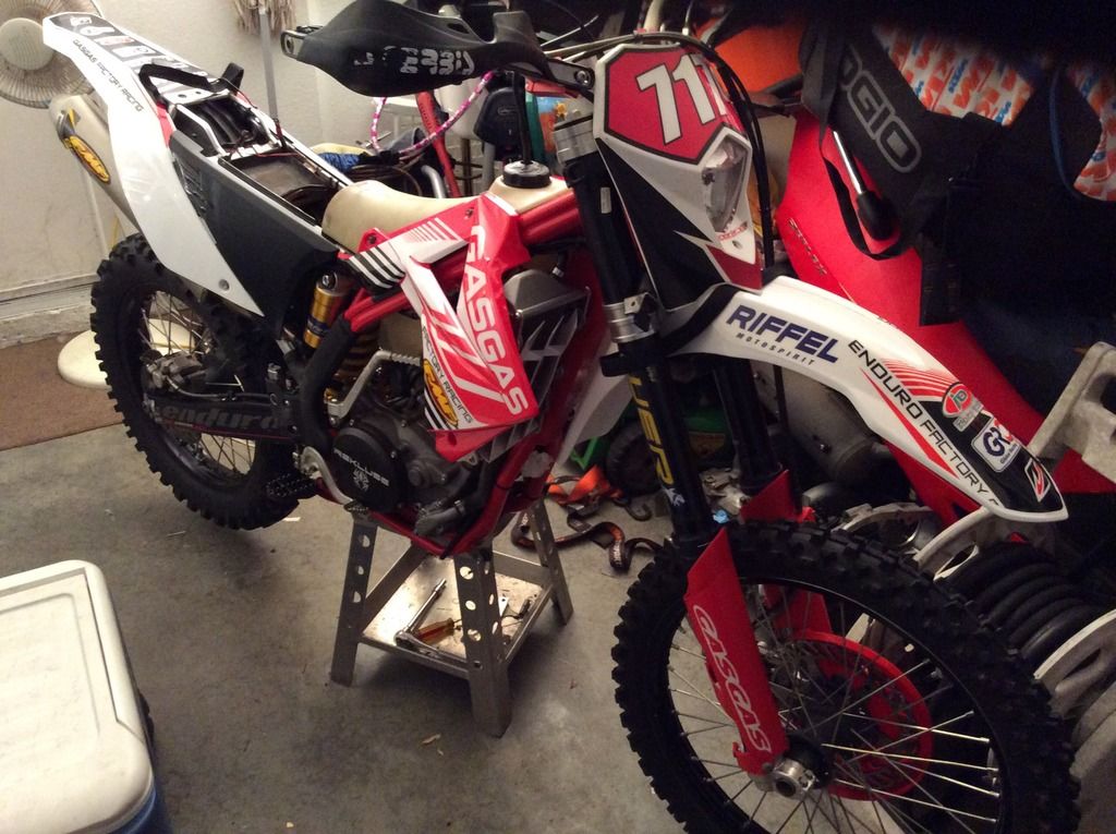
Here is the gasser before the I started taking things apart.
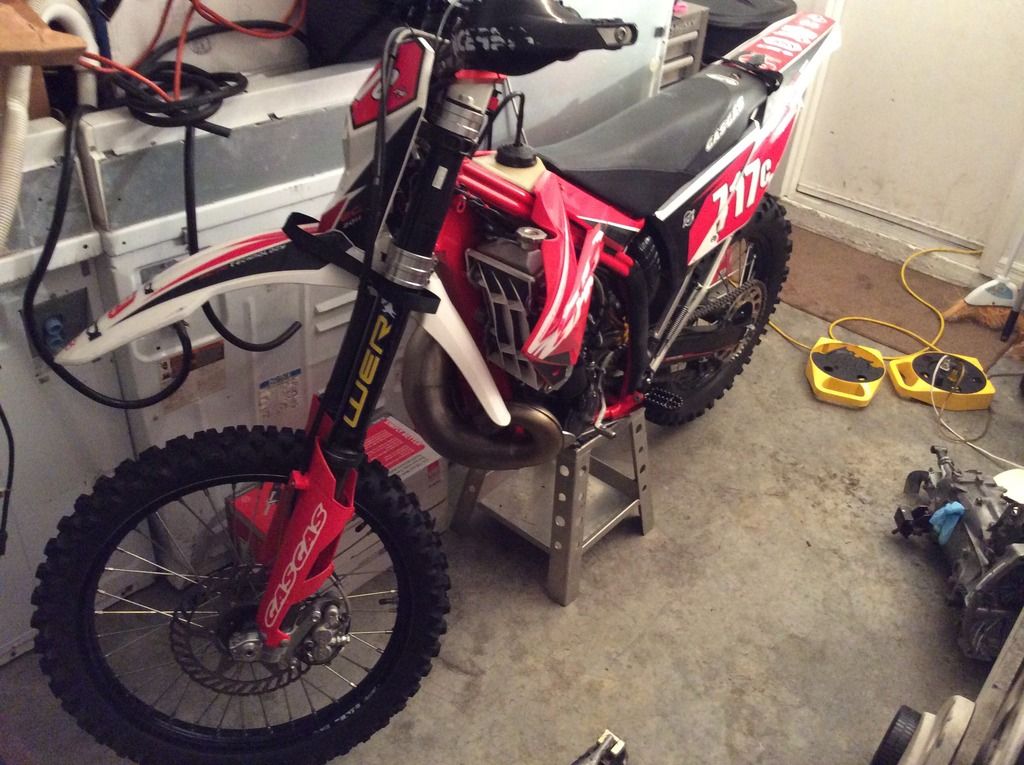
image.jpg1_zpszgotrdqp.jpg


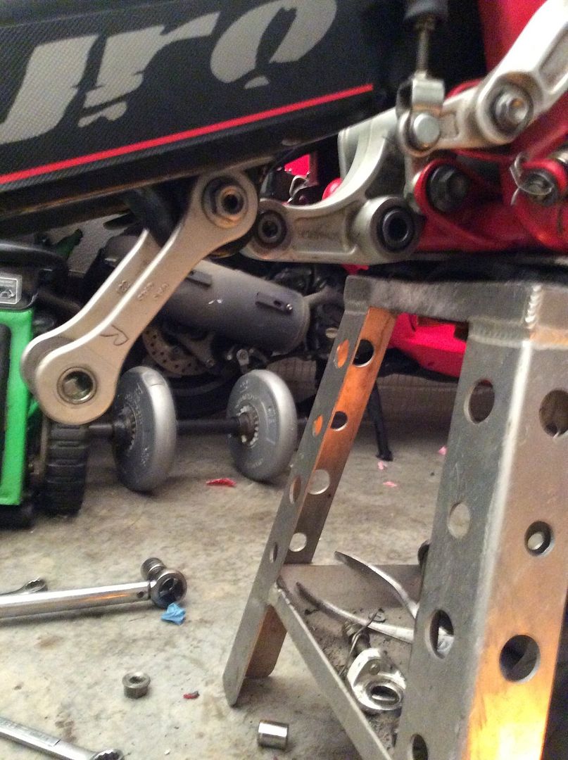
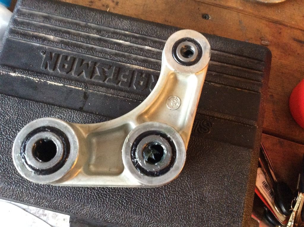
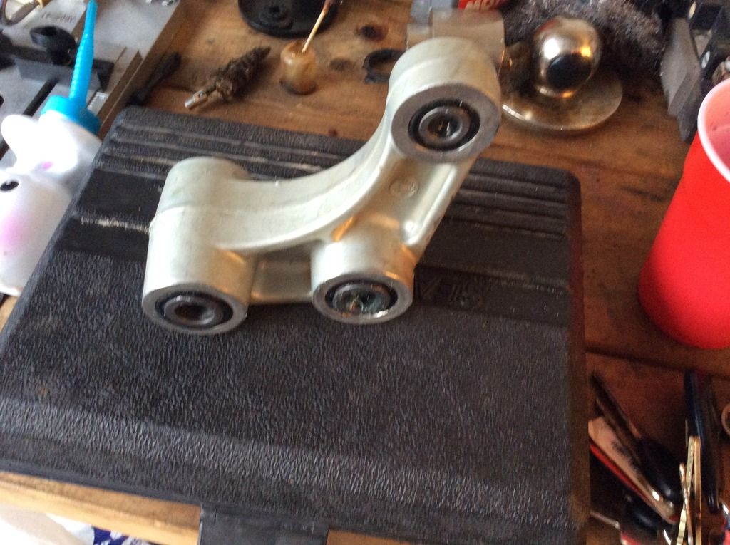
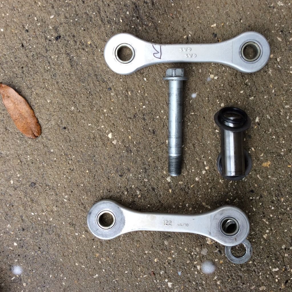
Here is the rear link,

image.jpg46_zpsmaule1yq.jpg


Swingarm bearings full of junk.

image.jpg5_zpsafzcrtzp.jpg


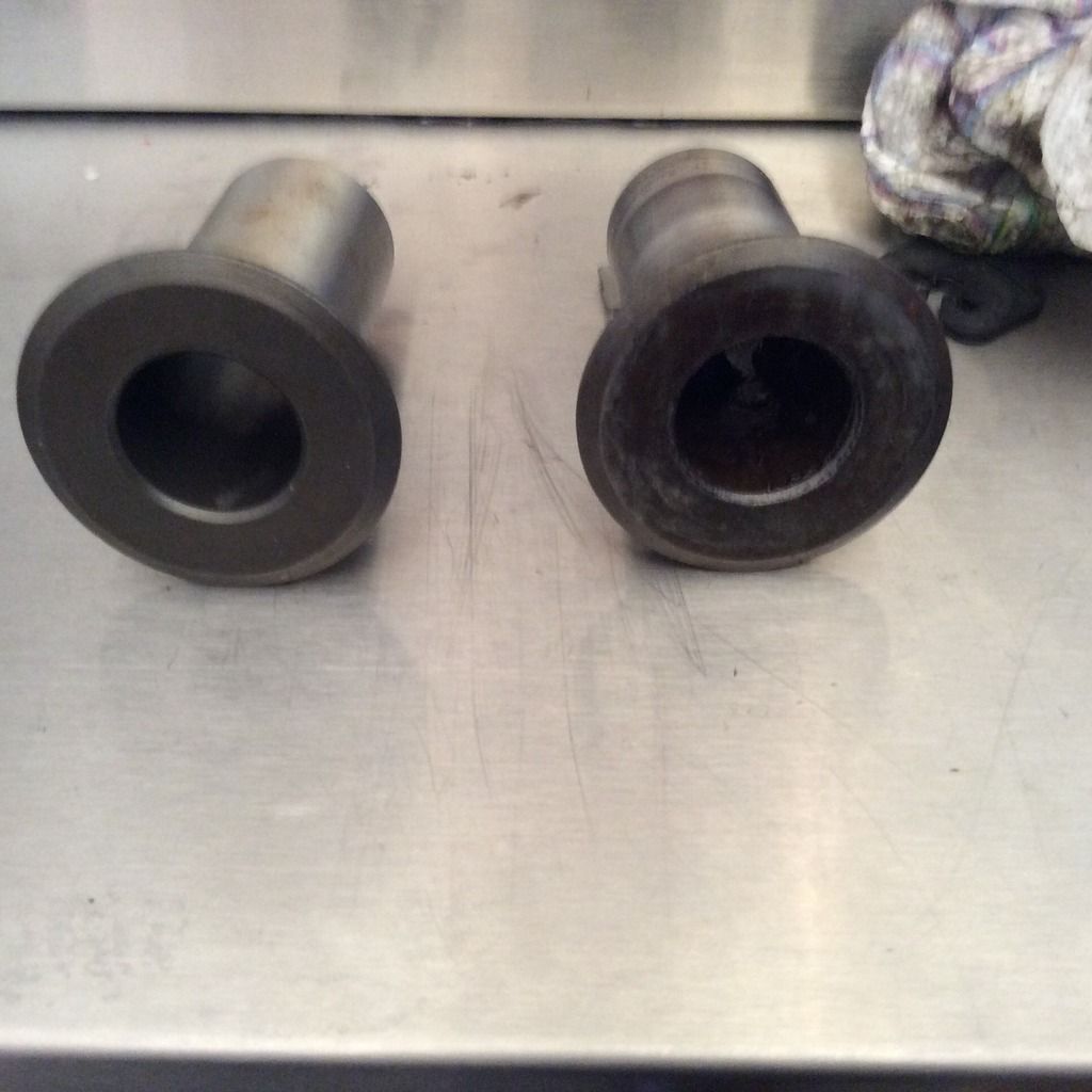
Here are the bushings, new one on the left and old one on the right.
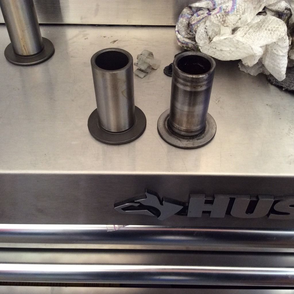
image.jpg34_zpsyqxtpt1i.jpg


image.jpg7_zpssuoefqis.jpg


image.jpg10_zps0odgxfyx.jpg


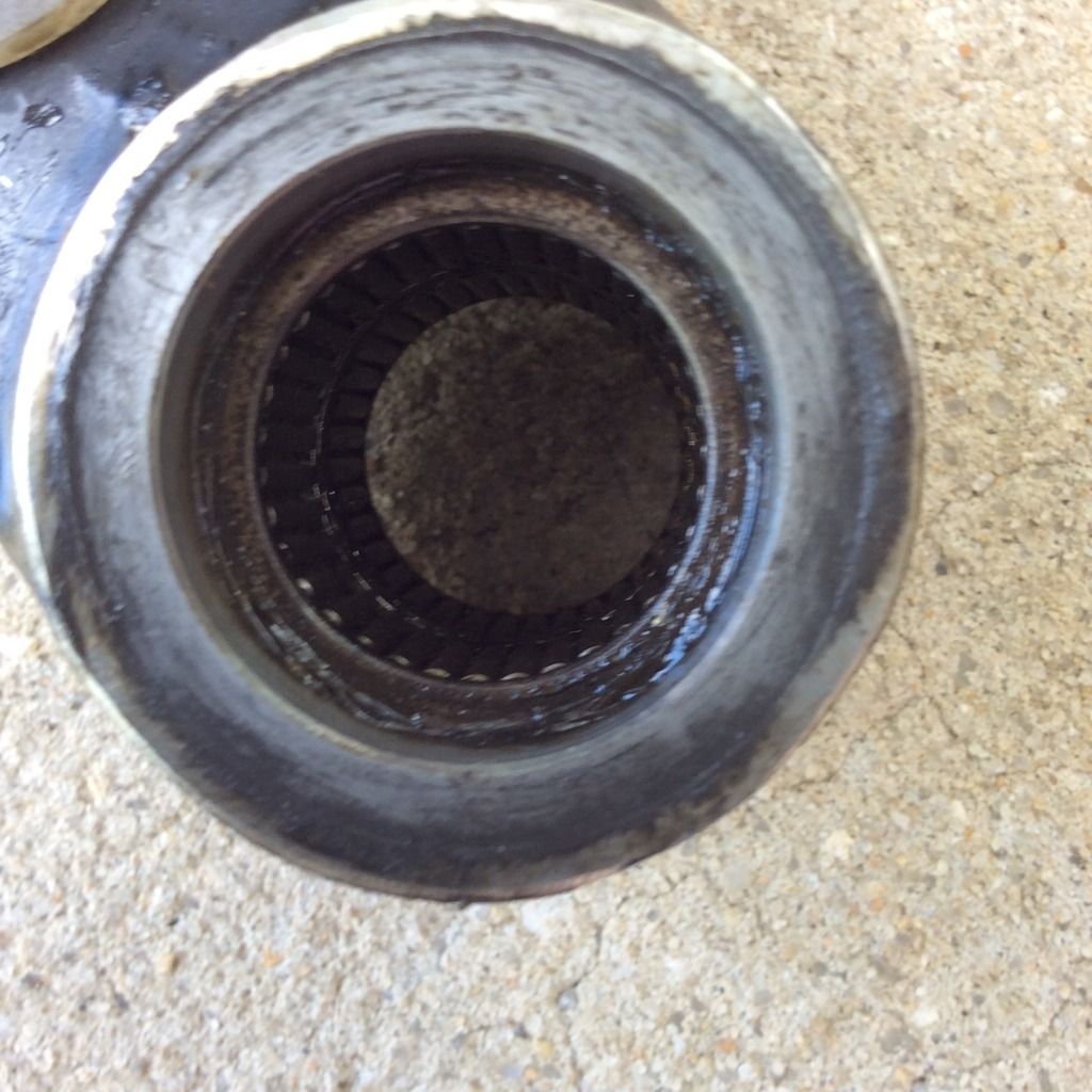
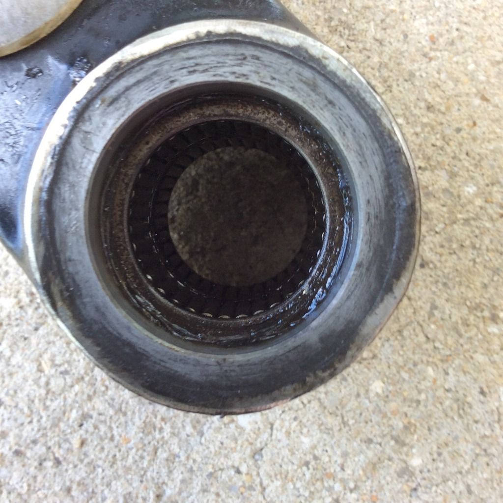
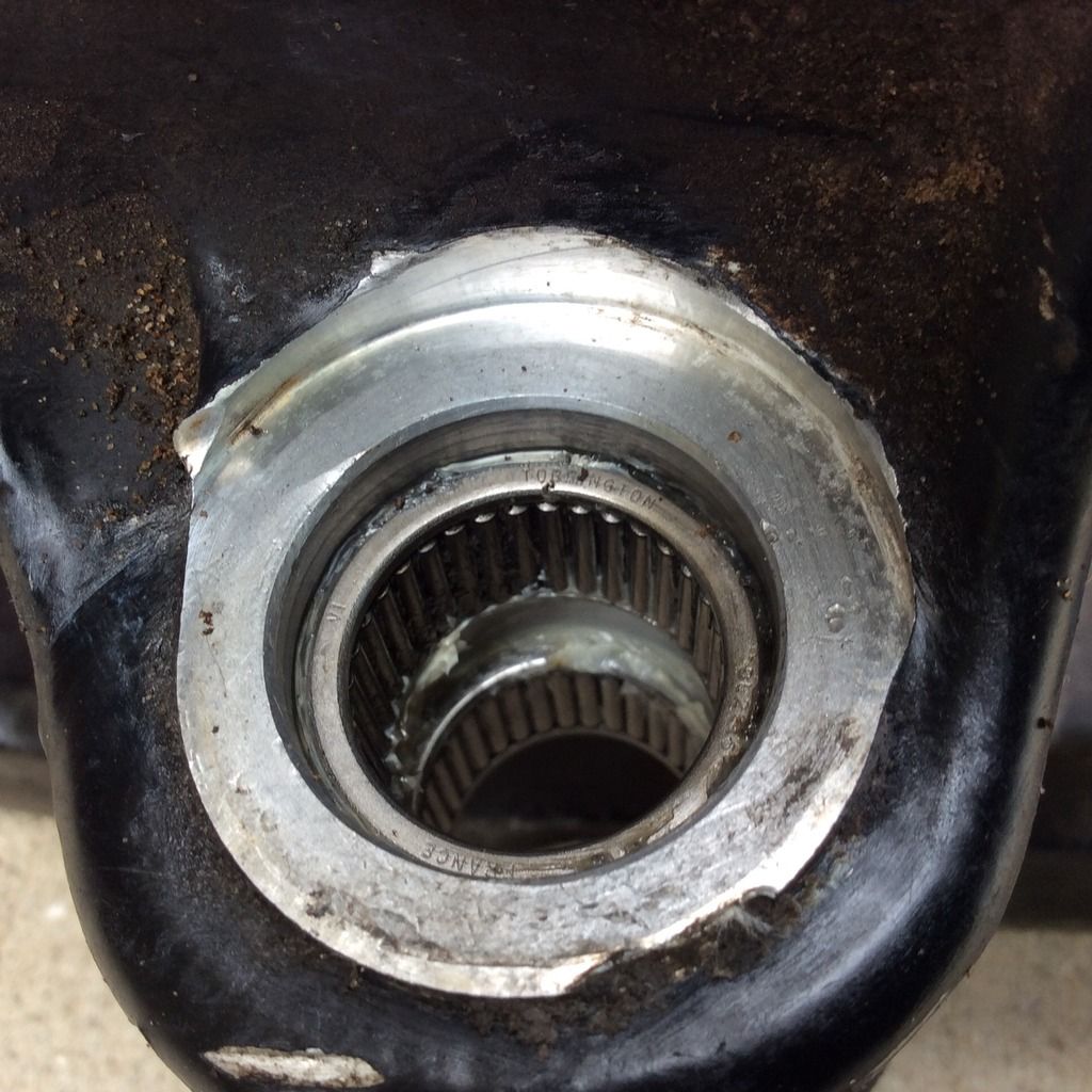
Here is the suspension bearing before cleanup,

After the cleanup, this is how they looked,
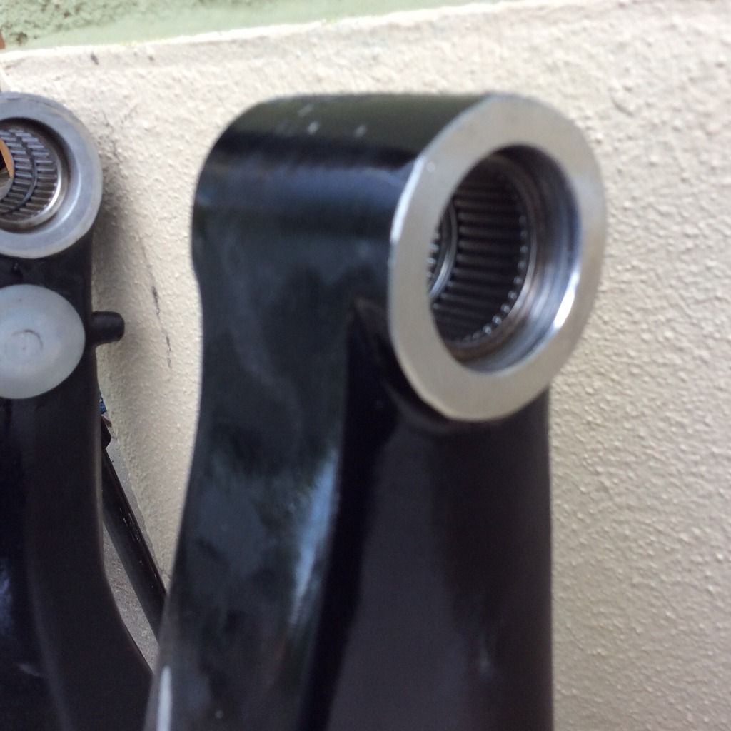
image.jpg23_zpsriklvb5q.jpg


image.jpg24_zpsdwmz8h0n.jpg


Suspension bearing after cleanup,

image.jpg30_zpskc08srxn.jpg
 
Last edited:
Here is the linkage after cleanup and repack,

image.jpg40_zpst6vvlshy.jpg


image.jpg39_zpsijrqmdrz.jpg


Here is another shot of the swingarm bushings, new on left old one on the right,

image.jpg37_zps8kubzazm.jpg


Disassembled linkage rods,

image.jpg32_zps223vjyim.jpg
 
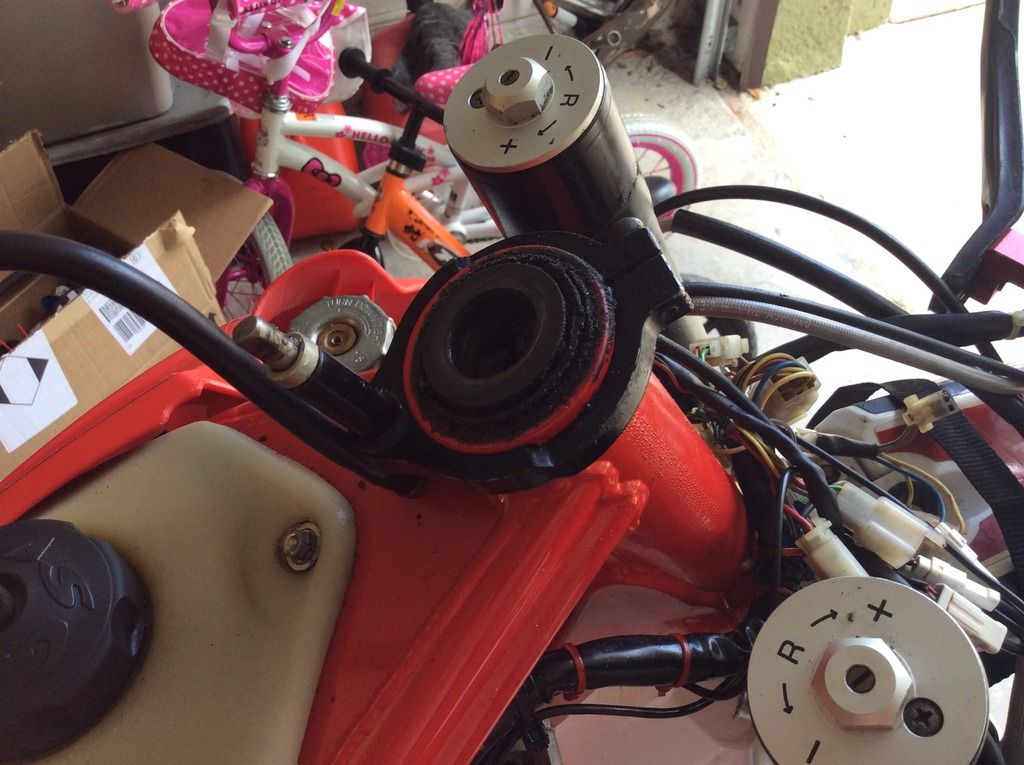
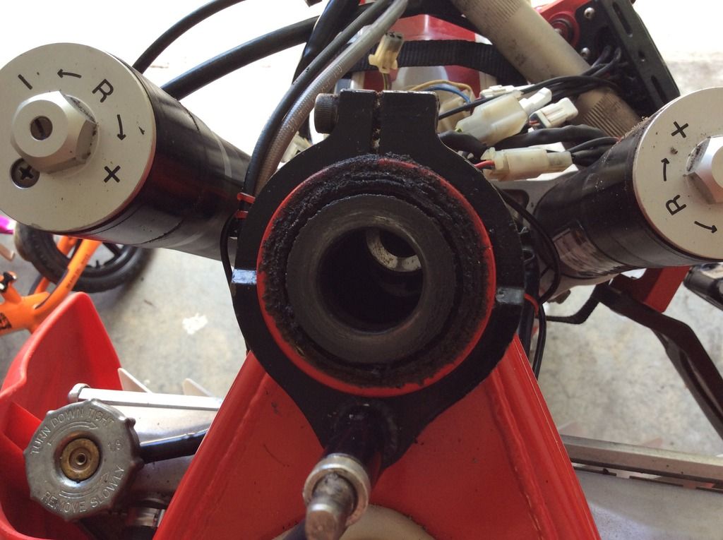
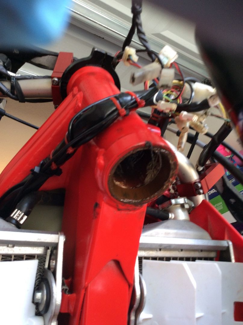
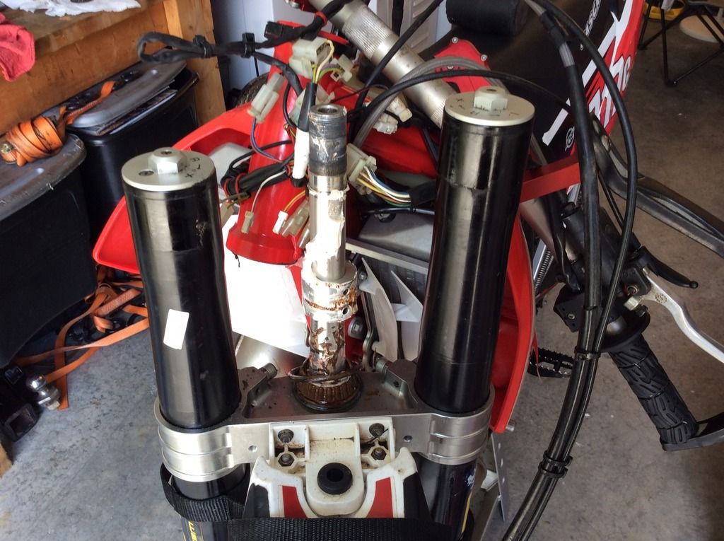
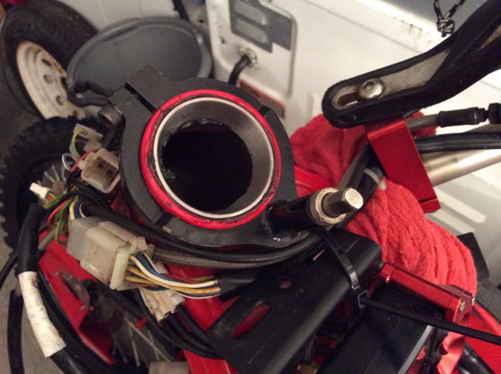
I then took the steering head apart,

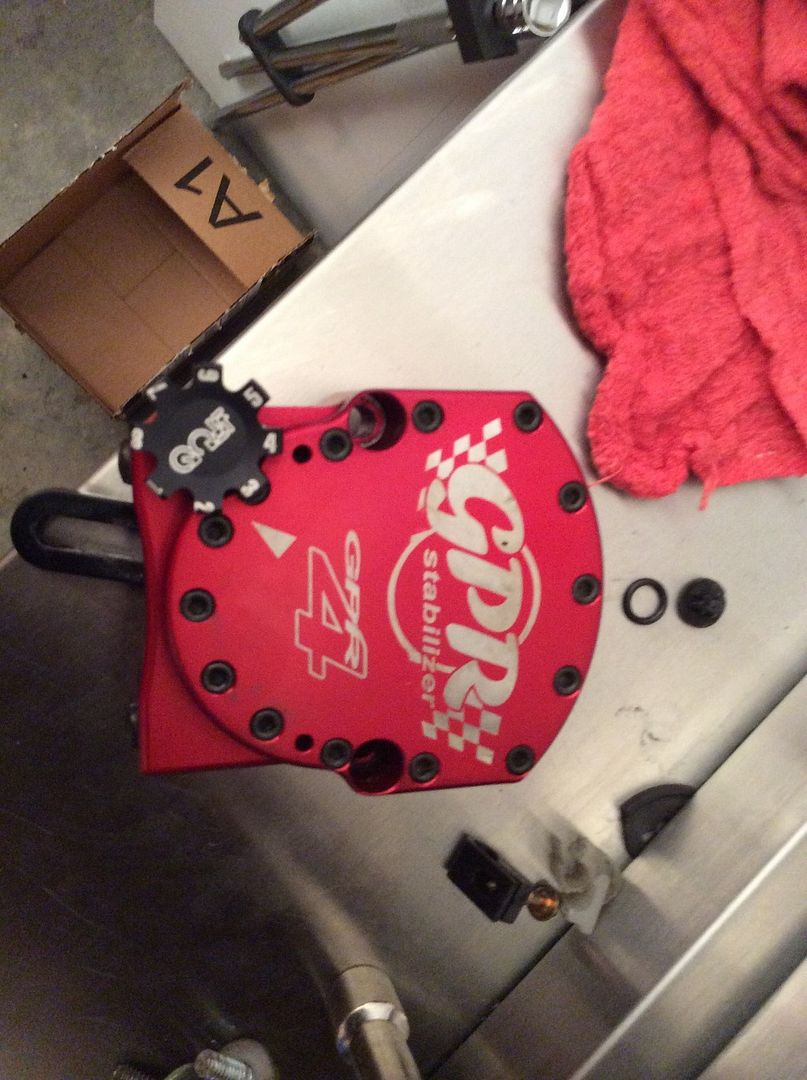
Off came the GPR and I sent it back for a free service,

image.jpg5_zpsabxfrh0g.jpg


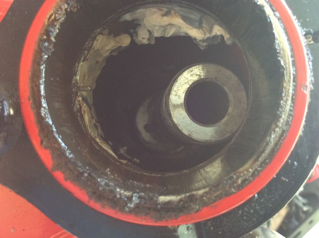
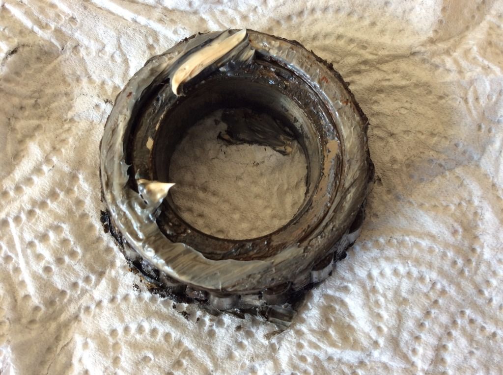
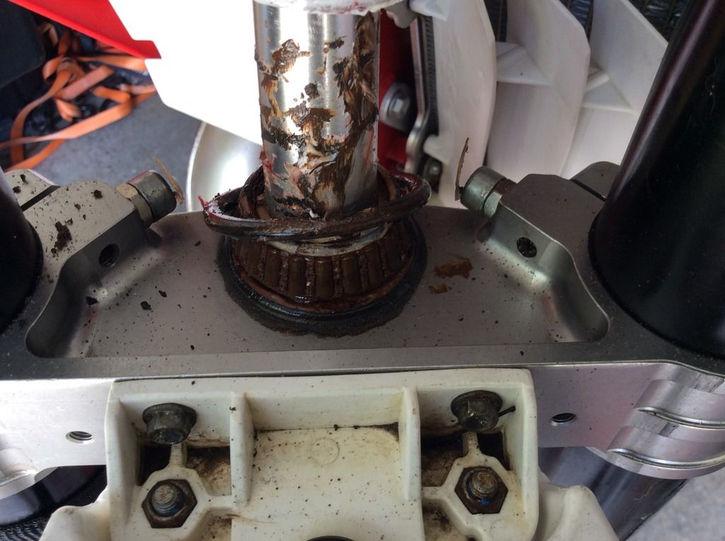
Here is the top steering head bearing, I was surprised how much crap it had on it.

image.jpg3_zpsamrhdvsj.jpg


image.jpg4_zpsjzto7pu3.jpg


image.jpg2_zpsnk0xpq20.jpg


image.jpg1_zps6dtse0lm.jpg
 
Last edited:
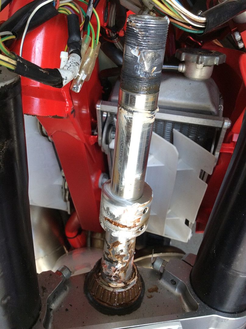
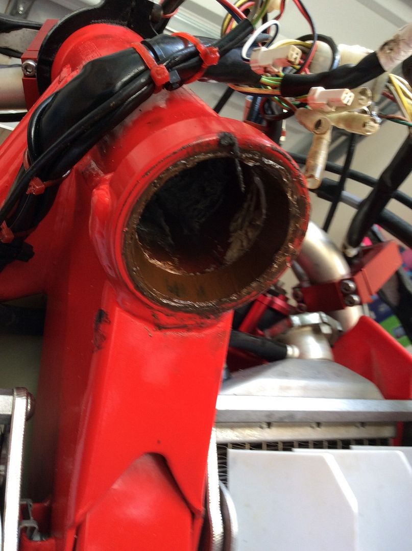
So, the top bearing looked kinda crappy, but the bottom steering head bearing was terrible. Check this out,

image.jpg13_zpskmowxsl8.jpg


image.jpg12_zpsylthivpj.jpg


image.jpg9_zpszymuvaw1.jpg


image.jpg7_zpsypjlyjrc.jpg


image.jpg5_zps0woe9ir1.jpg


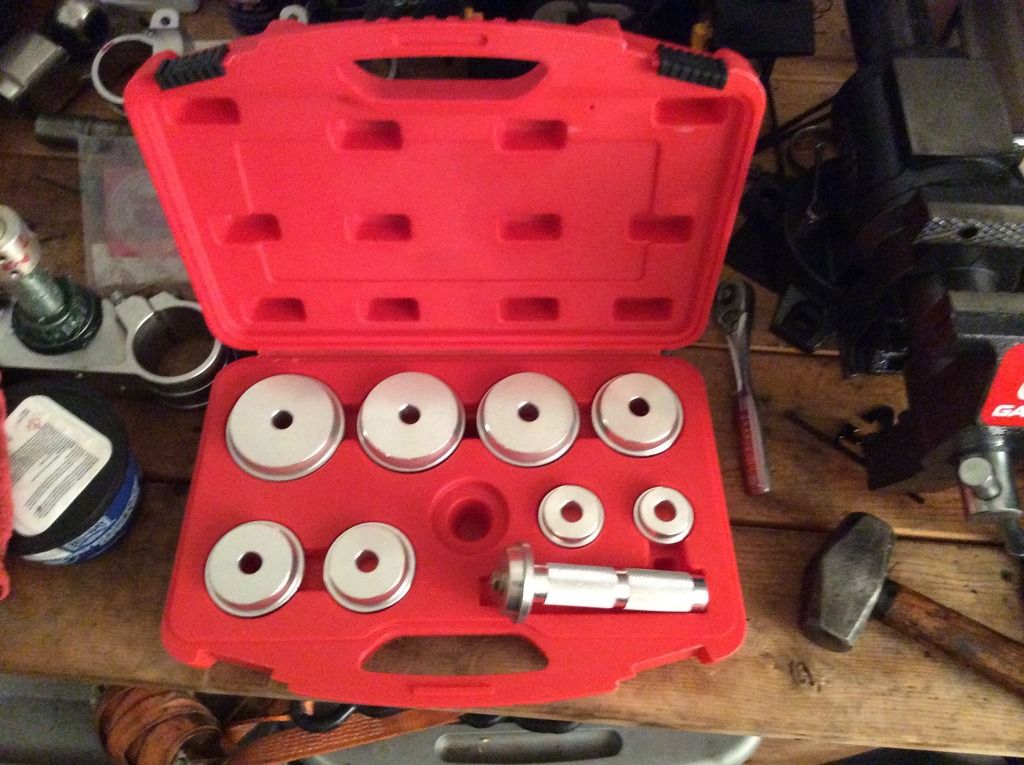
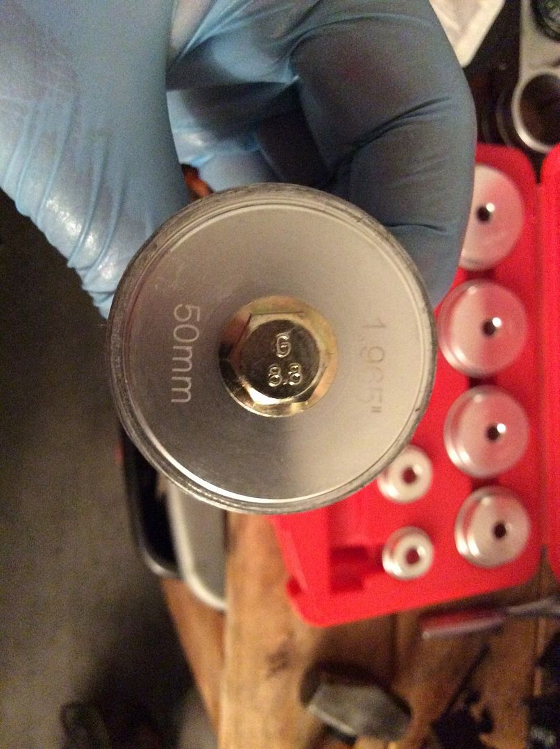
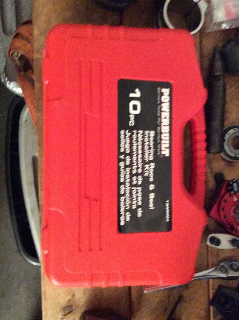
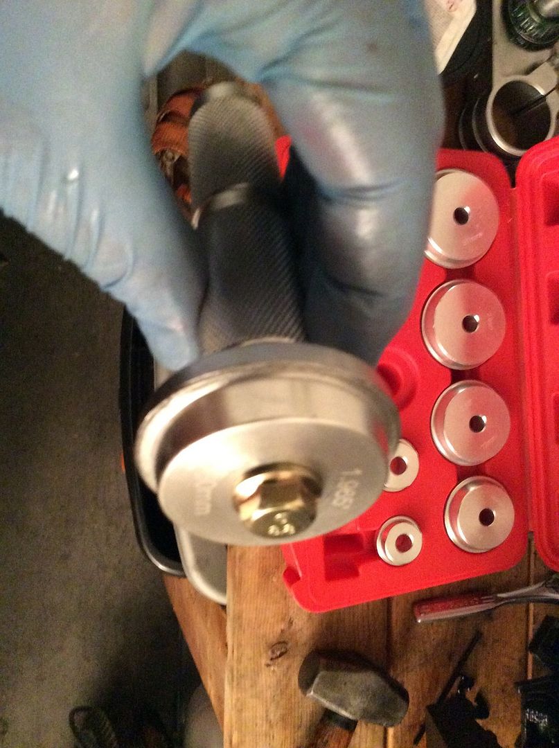
I cut the bottom bearing off with a dremel, then turned the old inner bearing upside down and used a vice to hold the inverted triple clamp and I drove the new bottom bearing onto the stem.The races looked very poor so I knocked them both out with a 12 inch punch. I bought a seal driver kit to install the new races.

image.jpg14_zps92aly3ic.jpg


image.jpg17_zpsteceloxd.jpg


image.jpg18_zpsab0utqmw.jpg


With this tool, each race can be installed in about 25 seconds. The new top race,
image.jpg16_zpsiioaz4lf.jpg

image.jpg12_zpsxzr9k5yp.jpg
 
Last edited:
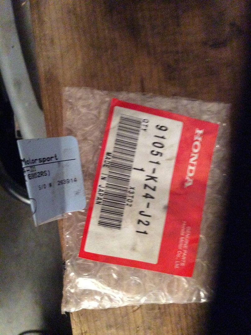
While working on the front, I pulled off the front wheel and pulled the bearing out. There were completely worn out. I replaced the front wheel bearing with new Honda wheel bearings, see the part number below. I got curious about the rear wheel bearings so I took them out too. The rear wheel bearings were in good shape but I replaced them with new SKF bearings and seals anyway.

Here is the Honda part number(which is for a rear wheel of a CRF 250F) for Honda bearings that fit the front wheel on the 2011 gasser.
image.jpg25_zpsyovpdfxb.jpg


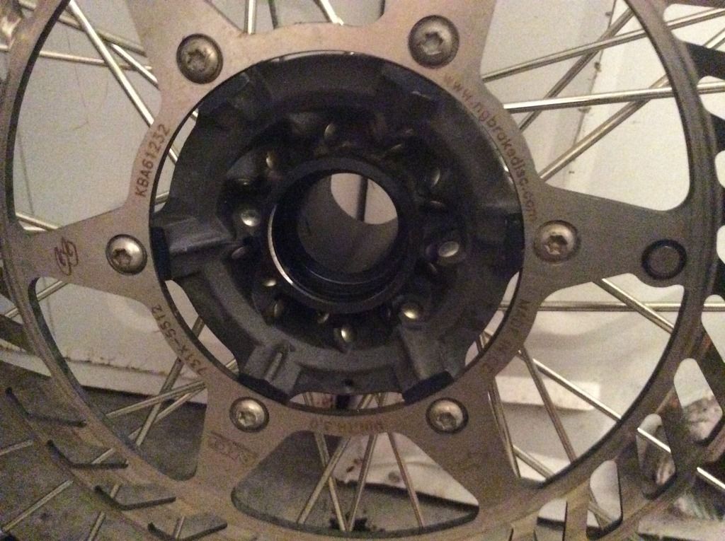
Front wheel after cleanup and before bearing install.
image.jpg24_zpszcndywly.jpg


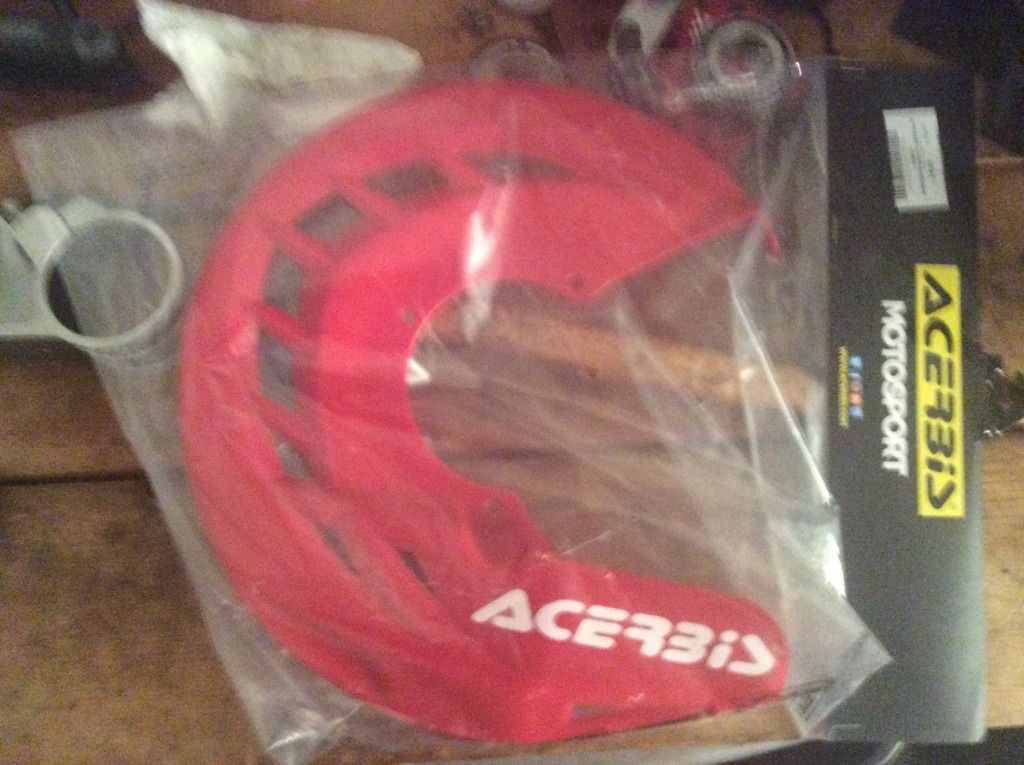
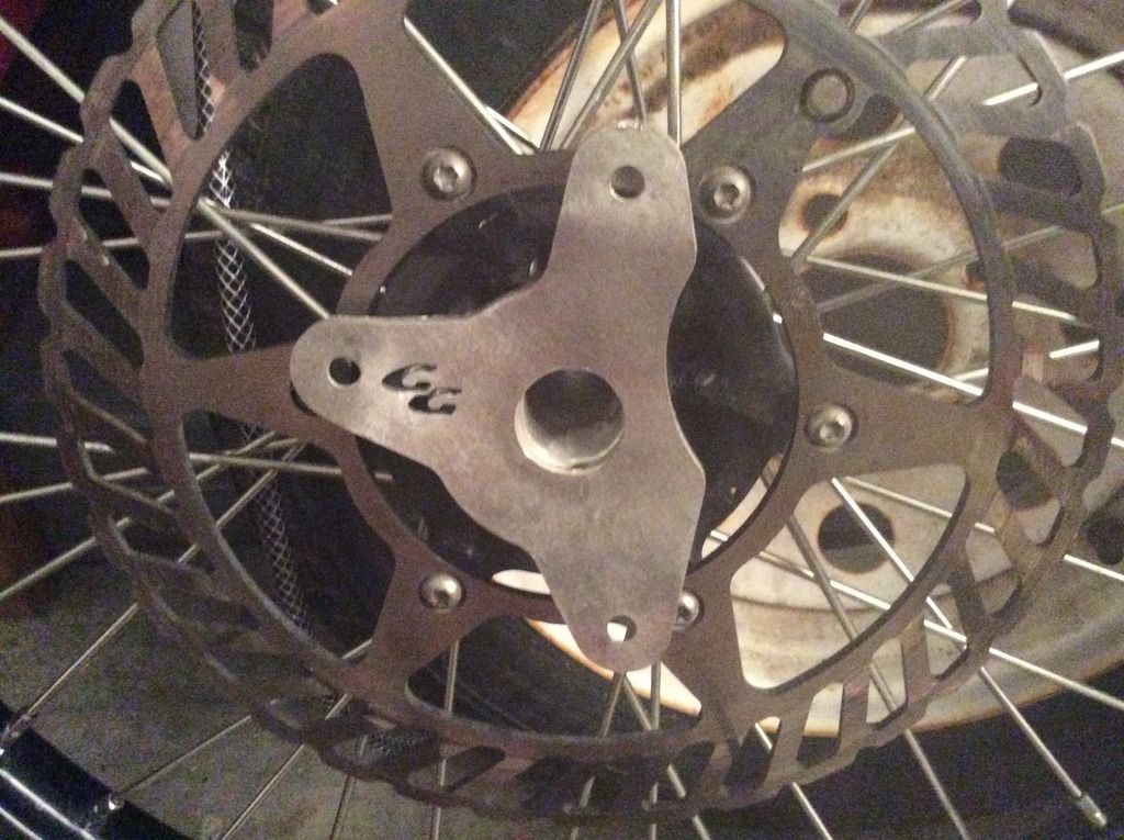
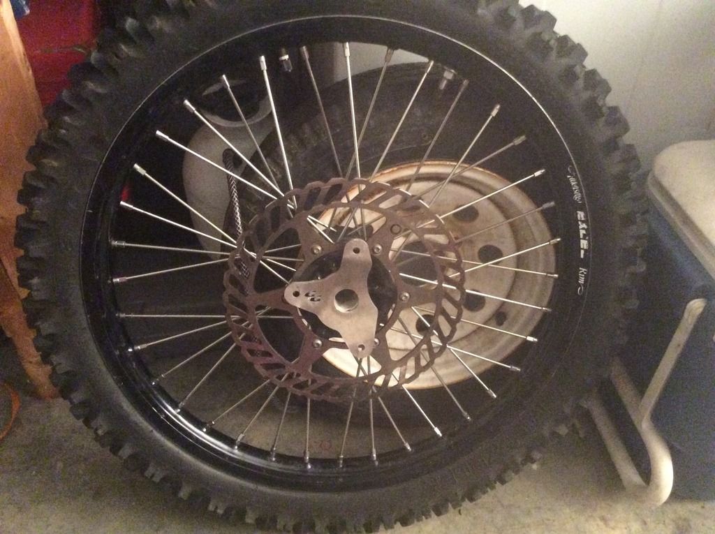
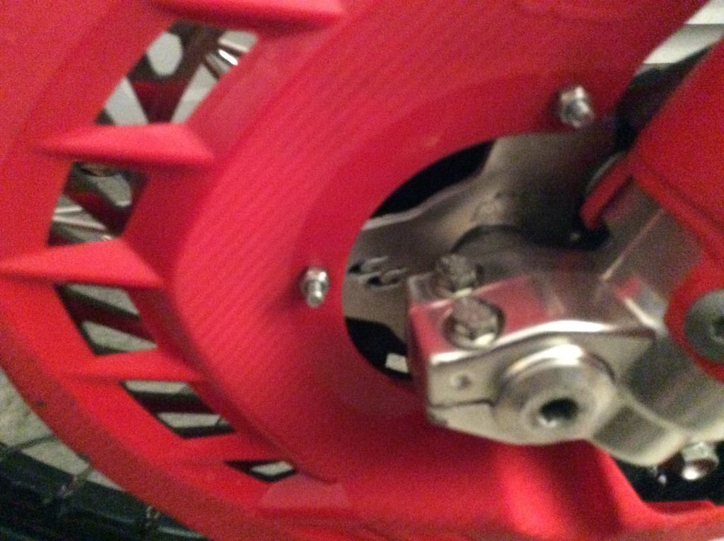
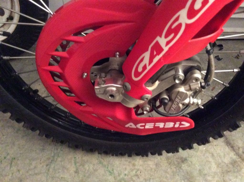
I also bought an Acerbis Front Disc Cover. Here is the cover,

image.jpg27_zps7jlh7kga.jpg


Here is the cover mount,

image.jpg29_zpsedj7dw4n.jpg


Here is the mount installed on the front wheel.
image.jpg28_zpspaufqpcm.jpg


image.jpg21_zpswryfdj9h.jpg


image.jpg20_zpsi0gs7hhh.jpg
 
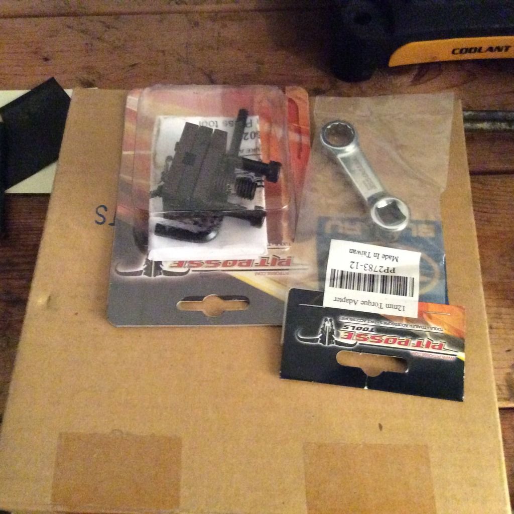
I bought some tools and some other parts for the rebuild.

image.jpg14_zps0ekwhuwp.jpg


image.jpg19_zpszgui6y1z.jpg


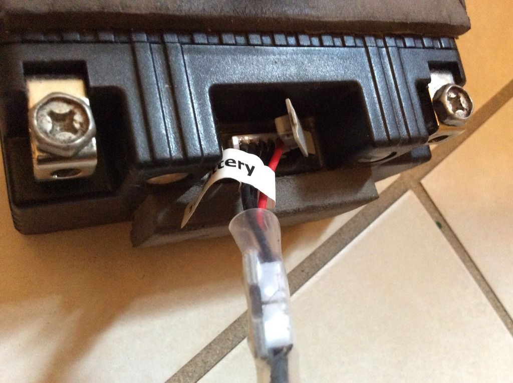
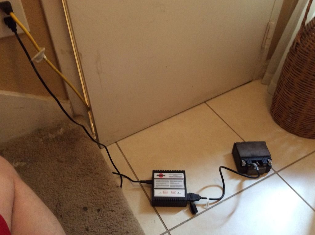
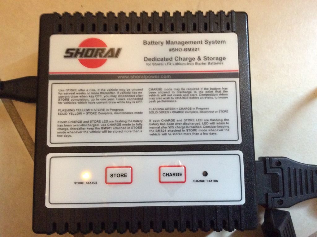
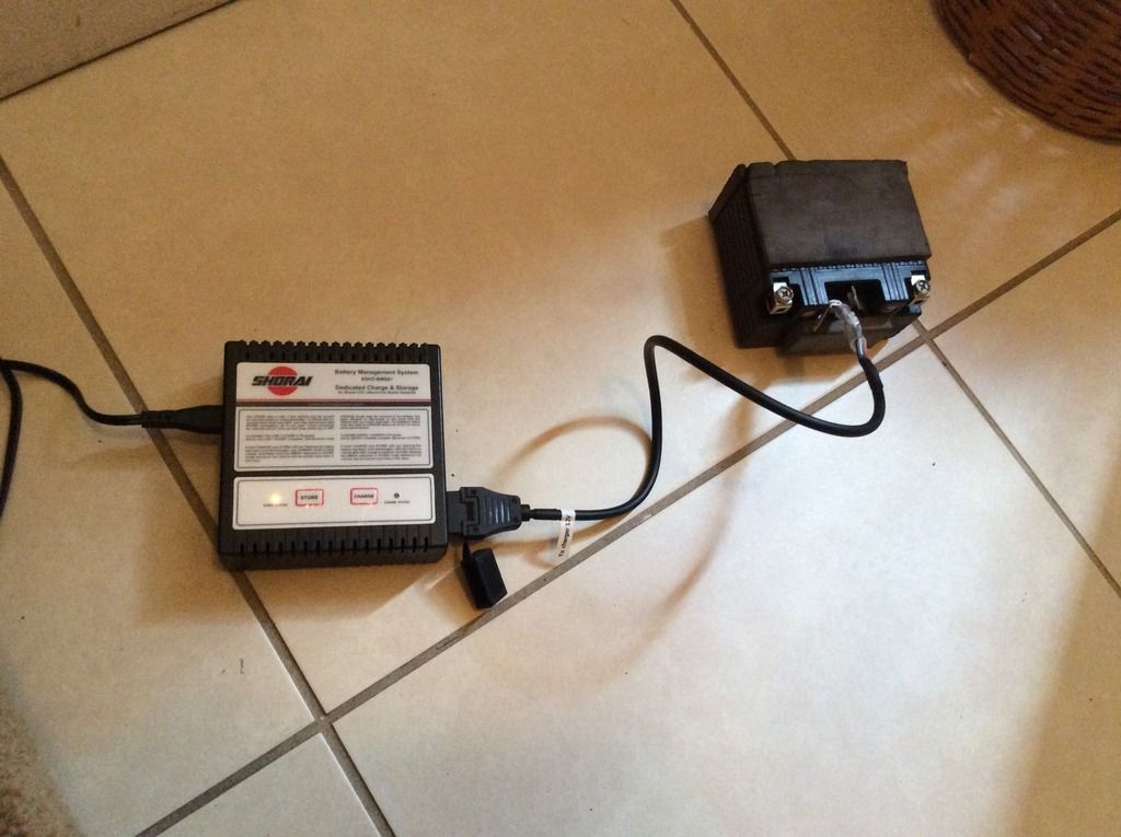
Shorai Battery Charger. I have had my shorai battery for 3 years and I never had a problem but it had discherged a bit. I hooked the battery to the charger and it quickly restored the battery to full charge. I have the charger set to the store function now. When I put the battery back it the bike, it will be simple to charge. The charger came with a cable extension which allows the battery to be charged without removing the seat.
image.jpg15_zpsqmd3yvae.jpg


image.jpg16_zpshwbzrxtl.jpg

image.jpg14_zpsiycjcfv3.jpg


image.jpg17_zpslabsbhxe.jpg
 
Last edited:
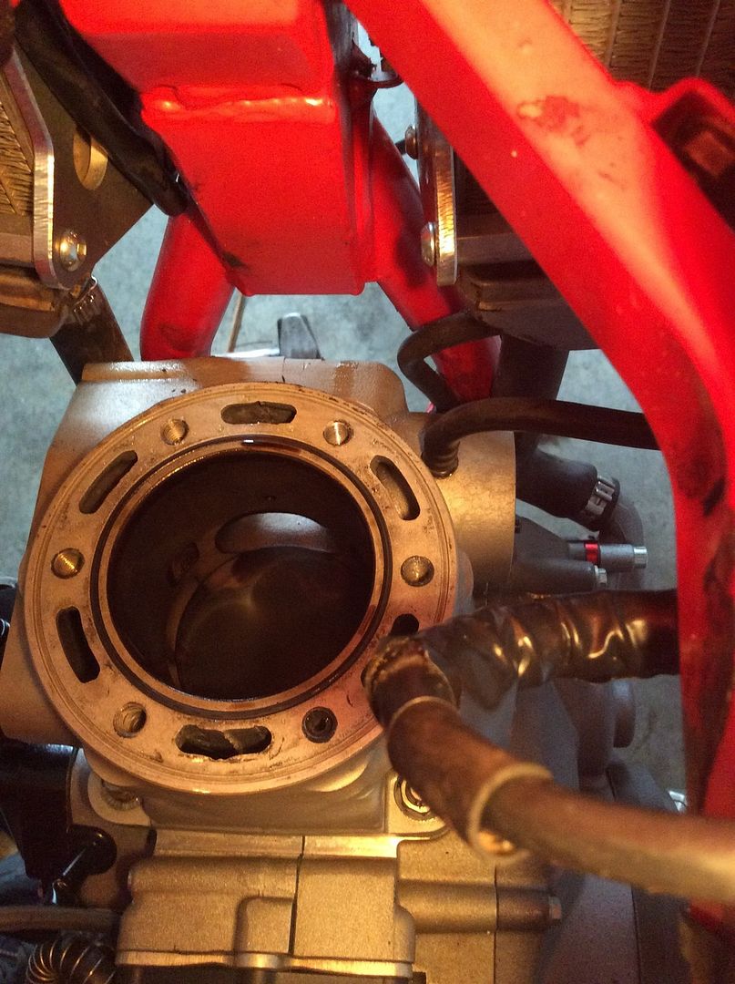
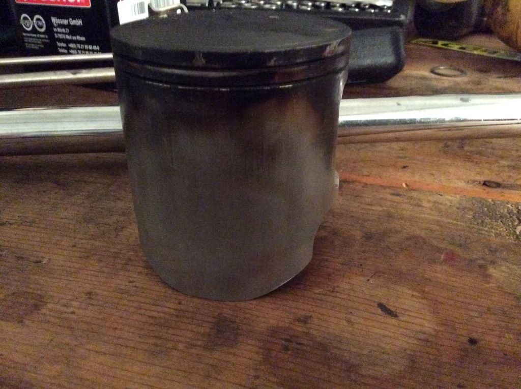
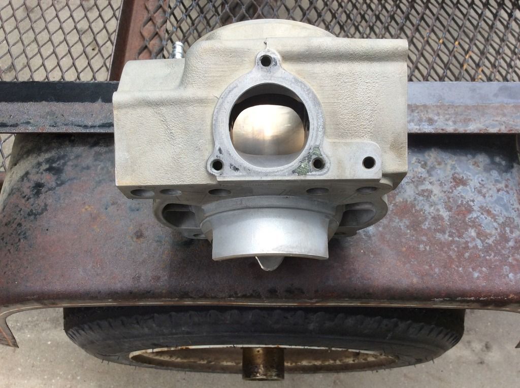
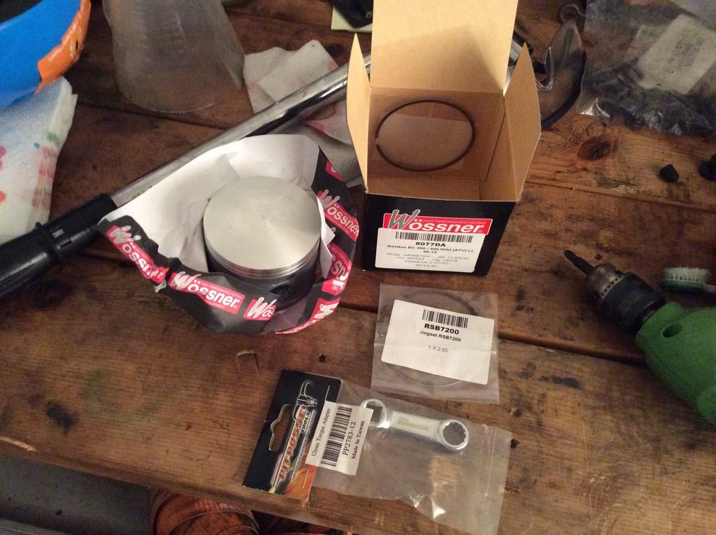
Next, I removed the topend. My bike has the "A" cylinder and this was the original piston and rings with around 150 hrs. The base gasket was the green .5 gasket and at BDC the piston was almost flush with the exhaust port. The endgap on the top ring was almost .8mm and the .6 on the bottom ring.

image.jpg3_zpsfpjct3zi.jpg


The piston had a lot of blowby and its seems like the very beginning of a little slap due to the rings being right at the service limit.
image.jpg12_zpsnva9tmtv.jpg


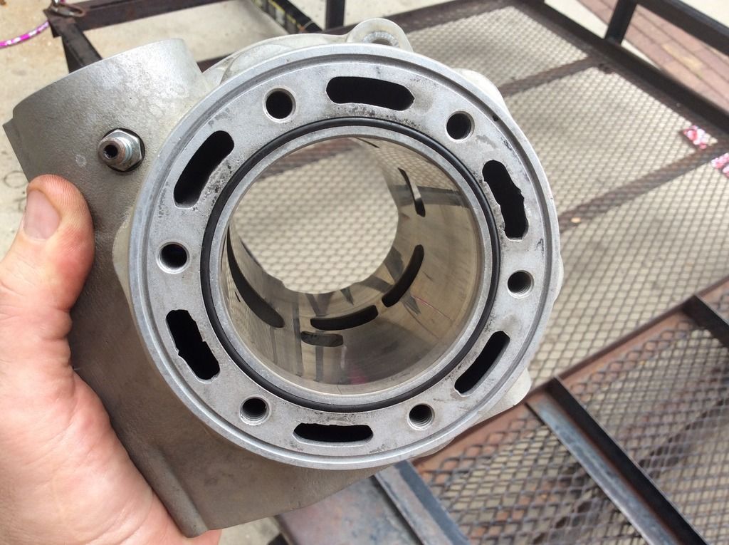
This is the cylinder after some basic cleanup, its full of crosshatch and ran my finger around the top inner part of the cylinder and I couldn't feel any edge which would indicate wear.
image.jpg6_zpsirqyusfn.jpg


image.jpg5_zpsdl6xdqs6.jpg


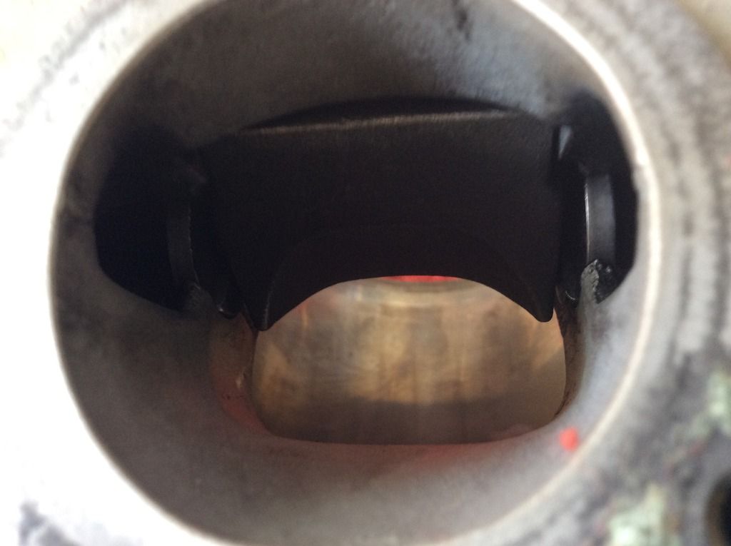
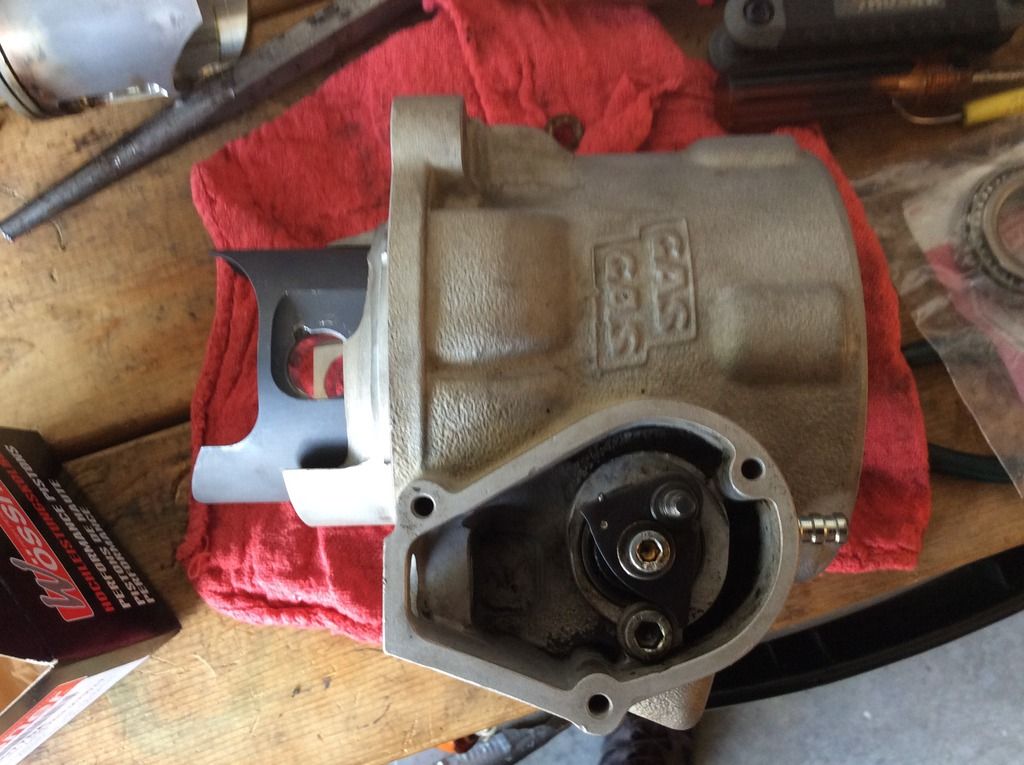
Here is the powervalve after being removed, cleaned and abjusted.
image.jpg7_zpsadv3faga.jpg


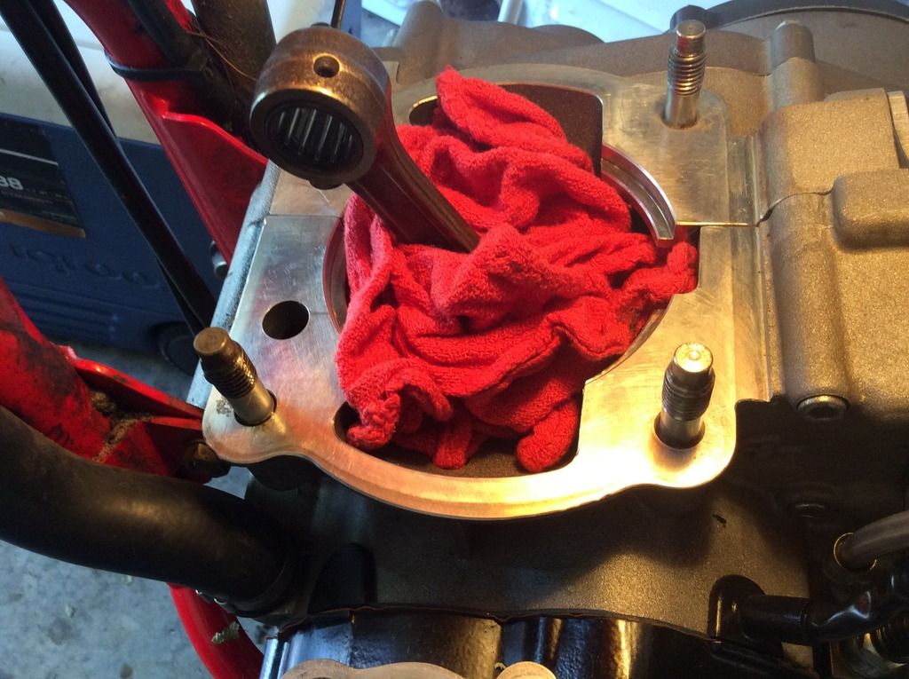
Case,crank and rod after quick cleanup.

image.jpg9_zpskmggc9oj.jpg


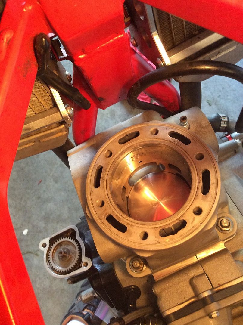
I installed the piston and rings into the cylinder, then lowered the entire assembly onto the rod and secured it with the wristpin then installed the circlip. (I'm going to buy the circlip tool that Jakobi uses, its too time consuming to do it with needle nose pliers.).

image.jpg5_zpsox9iyuwb.jpg


I installed the new piston and rings with a .4mm ring endgap using a .5 gasket(this was an oem gasgas gasket but it was black not green and I measured it to make sure it was the same thickness as the original gasket.)

image.jpg10_zpslvf0ihnd.jpg
 
Last edited:
Next I installed a new plastic and graphics kit.

image.jpg4_zpsn7piwvev.jpg


image.jpg3_zpsev0t5jvc.jpg


The right side air box cover is a little hard to fit. I'm going to put the heat gun on it tomorrow. Everything else fi
image.jpg6_zpsdnasvgav.jpg
ts well and the graphics went on without any problems.
 
Holy carp man, good on you! I'm muddling my way thru my 1st top end and it's taking a long time. Thanks for posting all the pics, they're a great reference :cool:
What's the tool you refer to for the clip? Going to search now, can use any help I can get during reassembly :rolleyes:
 
Looking great man, coming up on 200 hours on my 2012 and I plan to do the exact same thing!

It wasn't too bad it just takes some time. This weekend I am building a leak down tester and I am going to make sure everything is good to go. I have a few more small things to do then I should be good for the upcoming season.
 
Holy carp man, good on you! I'm muddling my way thru my 1st top end and it's taking a long time. Thanks for posting all the pics, they're a great reference :cool:

What's the tool you refer to for the clip? Going to search now, can use any help I can get during reassembly :rolleyes:

That is a Bux Tool in the 18mm size. However, you might not be able to use it if you are installing a vertex piston.
 
Where did you get the mount for the disc guard?

Did you like the mount guard? I was happily surprised when I looked it over. I got all the parts from Motocross Center except the Wossner Piston Kit. The mount guard came in a sealed package without a part number or any identifying names or numbers. It was about 42 dollars or so for the mount and Acerbis cover I guess it came from somewhere in Spain.
 
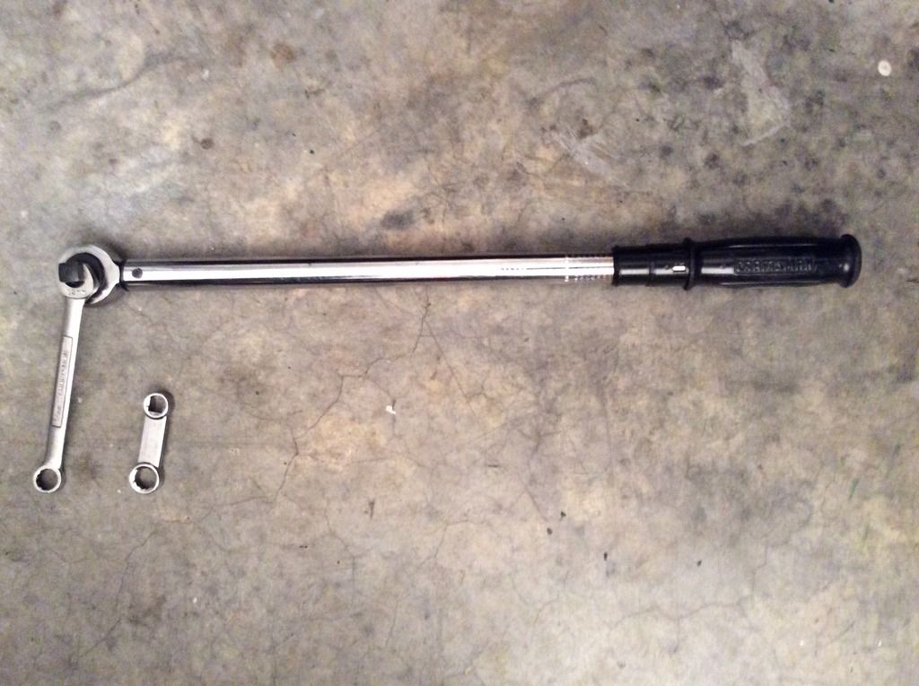
I was reading a 2008 post from this forum with great tip on how to torque cylinder base nuts without a torque wrench adapter. I have a 13mm Snap On Adapter, it works fine on the two rearward nuts on the cylinder but it won't fit into the small space within the powervalve housings to torque the front nuts.

Take a 13mm wrench, put the closed end on the nut, then slip a 1/2 torque wrench into the open end of the wrench and viola....you don't need an adapter. Set the torque wrench at a 90 degree angle to the regular wrench and you don't need to convert any torque values. It works really well.

You can see how much thicker the od of my snap-on is compared to the regular wrench.
image.jpg1_zpskpkayx4t.jpg
 
Take a 13mm wrench, put the closed end on the nut, then slip a 1/2 torque wrench into the open end of the wrench and viola....you don't need an adapter. Set the torque wrench at a 90 degree angle to the regular wrench and you don't need to convert any torque values. It works really well.

image.jpg1_zpskpkayx4t.jpg

That's a good tip. I will try that next top end.
 
Holy carp man, good on you! I'm muddling my way thru my 1st top end and it's taking a long time. Thanks for posting all the pics, they're a great reference :cool:

What's the tool you refer to for the clip? Going to search now, can use any help I can get during reassembly :rolleyes:

c-clipper

Great write up! Pics make threads
 
Please feel free to add comments or advice.

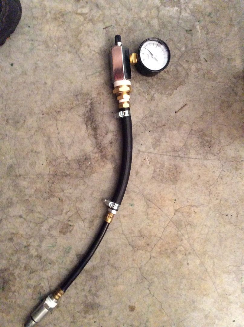
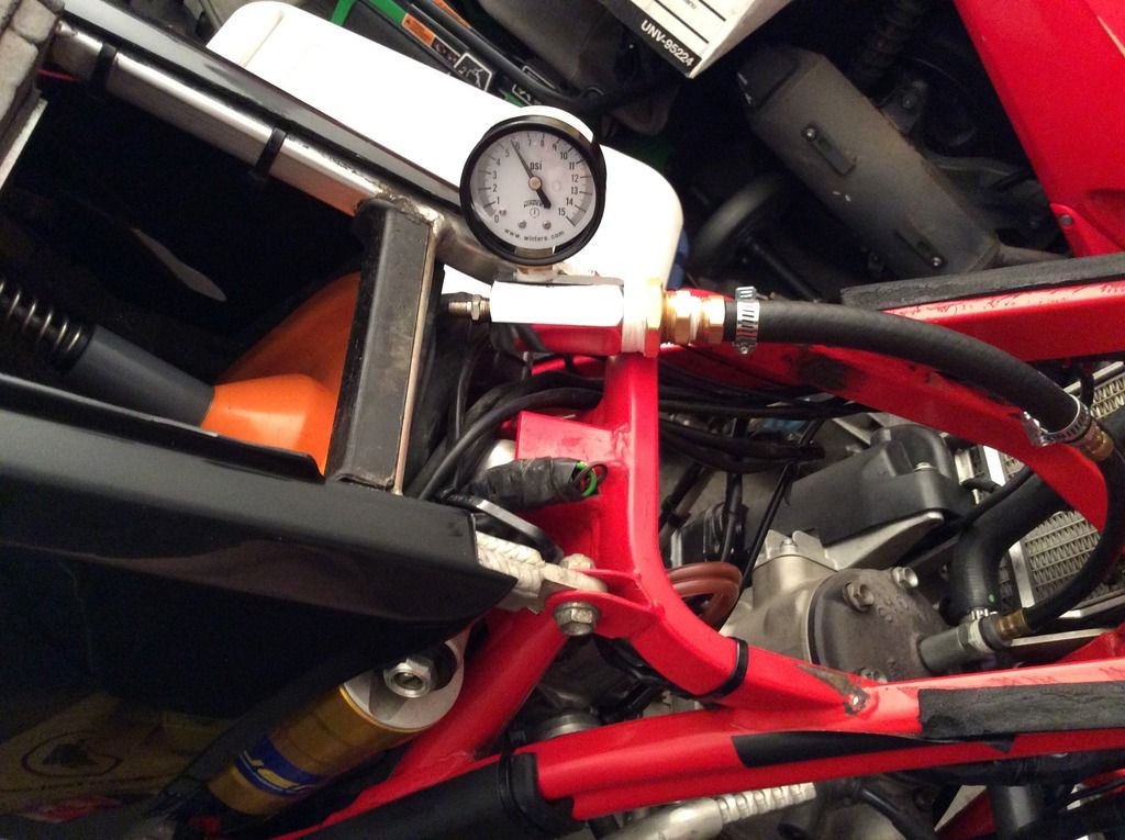
Here is the leak tester that I put together today. It cost about $25.00 total and it worked really weli. This is what I did on my bike. Make sure that you pressure test the tool before you attach it to the engine. Set your engine at BDC, block off your intake, exhaust and powervalve vents. Use a handpump and don't go beyond 5 PSI because after you stop pumping the pressure can still climb about 1 PSI. Any more than 6 PSI can blow out your main seals.

When I attached the gauge to my engine the engine held 6 PSI for 15 minutes with almost no loss( about 1/10 of 1 PSI ). I completed three tests with the same results. So, my engine should be solid after this rebuild.


image.jpg4_zps7vdpccxb.jpg


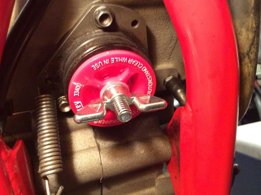
Here is the 1.5 inch mechanical pipe plug for the exhaust.
image.jpg1_zpsfsi7uofl.jpg


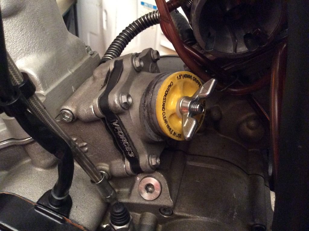
Here is the 1.5 inch mechanical pipe plug for the intake,

image.jpg2_zpsnkzpj0fv.jpg


image.jpg5_zps6e0danpb.jpg
 
Update; when using the 1.5 mechanical pipe plug on the intake, you need to remove the intake boot. When inserting the pipe plug,loosen the plug bolt then insert the pipe plug into the intake,then lightly tighten the pipe plug bolt, it's already a tight fit but don't tighten it too much or it will take a strong tug to remove it.
 
Back
Top