DC conversion - not floating ground

johnm

New member
Hi all - first post

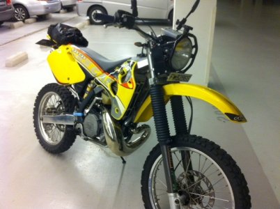
Just bought a zero mile/hour 2000 EC200, had it a couple of months and have got fed up with dim lights and indicators that do not function with the lights on. So did the DC conversion without floating the ground.

Parts used

Trail Tech regulator/rectifier
Trail Tech battery
Part plate of a Trail Tech battery bag
Velcro anchor straps - two
Car flasher relay
Bullet connects
Spade connector
Wire, red and black
Cable ties
Heat shrink

Here is what I did - aim was no holes drilled and completely reversible

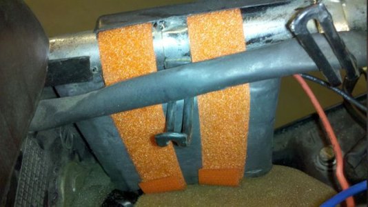
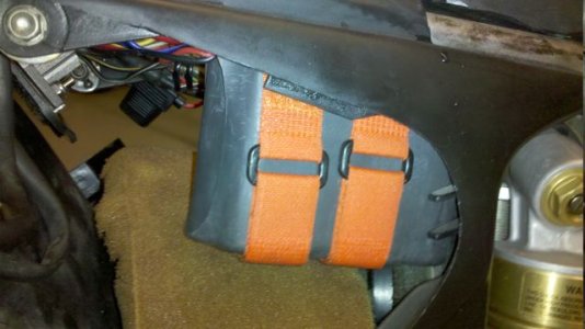
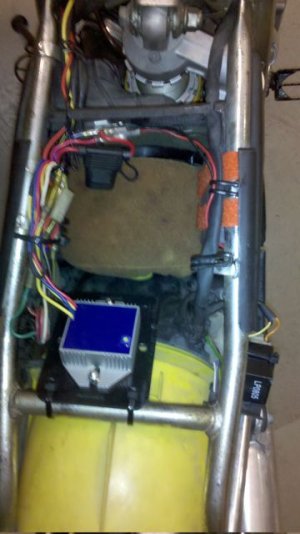
Battery install - lot of head scratching for location, but decided on right hand side of air filter box, was attached using two velcro anchor straps. See images Battery 1 & 2.

Install voltage regulator rectifier
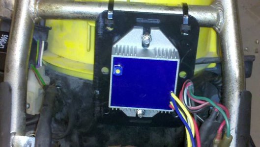
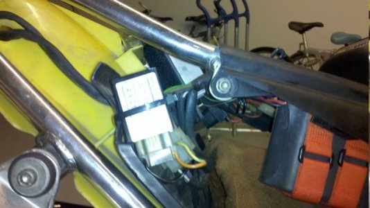
Installed on rear/upper bar in air filter bay, this was mounted on the plastic packing plate which came with the battery bag (bag not used), this plate was cable tied to bar. See Rectifier Regulator mount.

Next located the AC regulator and removed
Located earth for lights/indicators/horn etc - this was located above AC regulator; remove from frame. sample check all earth wires to ensure are not connected to the frame - I found a secondary earth through the handle bar switches. Resolved with insulating tape placed on handle bar before mounting switch.
Move alternator wires yellow and white from under tank to air filter housing area (they should simply unclip from frame).

Modifications to loom
Earth wire remove eye connector and replace with bullet connector.

Install of wiring
Battery positive (red) take wire to where the original AC regulator output connected to loom, also connect Trail Tech Reg/Rec red lead
Battery negative (black) connect to Trail Tech Reg/Rec blue lead
Remaining Trail Tech leads
One yellow connect to white alternator wire (yellow no longer used)
Other yellow to original earth point on frame (where AC regulator and loom earth were mounted)
Black wire to the new earth wire where you attached the new bullet.

Flasher Relay - two connectors will have to be swopped over depending on the type of flasher relay you have.

That's it - tidy wires, install tank and panels, all electrics can be tested prior to start

My results
Every thing off
Battery volts 12.5

Lights on for a couple of minutes voltage dropped to 10 volts

Engine started
Every thing off for a couple of minutes 13.5 volts
Lights and flashers on stays at 13.5 volts at close to idle speed
 

Attachments

  • Battery 1.jpg
    Battery 1.jpg
    45.5 KB · Views: 639
  • Battery 2.jpg
    Battery 2.jpg
    39.1 KB · Views: 568
  • Rectifier Regulator mount.jpg
    Rectifier Regulator mount.jpg
    43.6 KB · Views: 649
  • Flasher.jpg
    Flasher.jpg
    43.5 KB · Views: 611
  • Finish.jpg
    Finish.jpg
    39.9 KB · Views: 644
Great first post! Welcome. This should be "Sticky'd" and/or be copied over to the technical articles on the main site.
 
Lights next

Thanks guys.

Looking for better lighting next - possibly a Ricky Stator 8", with dip and high beam.
 
Thanks for posting this. I am heading down this same road soon. Waiting for parts to trickle in and time to work on it.
 
John,
I have a battery setup in my 300 and am running a Hid setup.
I used a turntech 5ah battery and ended up floating the ground in the stator but the light setup doesn't even effect the battery charge when bike is running and only drops it a little on start up when bike not running.
For under $100 Aud these are the go. I am using the standard 07 light right now but have a 7" round light I will be adapting for next season.
Plenty of light as is though for trailriding(racing too really).
Cheers Mark
 
For next year I'm going to try and run two Vision-X LED lights off my 2K-2 with a rect/reg and a capactor filter, no battery. I'll just make an isolated module in a small box to connect between the bikes AC and the lights, easy to R&R as needed.
 
I consider the term "floating the ground", to be a real misnomer. Does the GasGas normally have part of the windings split out to feed a small rectifier? This would create some DC, but I don't know what it would be used for on a bike without a battery.

There are only two functions in an electrical system: ignition and lighting. Ignition is taken care of through a separate winding and the CDI. If the lighting is fully AC, there is only a regulator installed to limit the voltage level. This prevents burning out bulbs at high RPMs.

On many bikes, the lighting coils have a common ground partway through the windings. Above the ground point is AC. Below the ground point is AC too, but gets fed to a rectifier and changed to DC for battery charging. This is typically only a small amount of current and not suitable for any real load like a big headlight.

Floating the ground is a misnomer because the ground is just being moved to the "bottom" of the windings. You take a larger rectifier and change the entire AC output to DC. "Moving the ground" would be the correct term.
 
The Kokusan 2K-3 has no separate small winding for DC. There are two output windings and a common that is referenced to the stator frame(motor/chassis). The 2K-2 has just one smaller 35W output winding. A DC conversion is just like building a linear DC power supply from a transformer, bridge rectifier, filter, and regulator. The Trailtech module just integrates these components except for the filter as the battery takes its place. In either case the DC output is isolated from the AC input to the rectifier. If the grounds were connected, one pair of diodes in the bridge would each be shorted, one during 0-180 deg (+) and the other during 180 - 360 deg (-) of the sine wave, bypassing the DC system load.

So you are isolating the grounds. If you choose to have a DC chassis ground then it must be done with the stator mod. I'm pretty sure the white and yellow outputs are out of phase (different poles) and not just a center tap type arangement of a single winding. The term "Floating" the AC ground or removing its reference to the chassis is just a way of saying "Isolating".
 
The term "Floating" the AC ground or removing its reference to the chassis is just a way of saying "Isolating".

Any thoughts on how the estart bikes will be done? I expect a manufacturer would not isolate the DC ground.
 
It could go either way. If the current bikes like the Six Days have all the Euro street gear, they have a small half wave rectifier anyway to run the DC horn and flasher for the directionals. If they just have basic lights like the XCs, they just run on AC. Either could eaisly run on DC, and this would be done with a different isolated ground stator configuration.

Its easy to tell, for those that have seen the bikes does the battery negative lead get grounded to the frame? If so its a DC gnd system with a different stator. If not, the DC ckt for the battery and starter is isolated and the rest of the system is AC.
 
Tp answer the questions with respect to the earths

Difference between floating and non-floating ground

The original system is a frame grounded AC system, the ground before regulator and after is common; because the system remains an AC system, this is ok. One side the generator is earthed to the frame and all components within the electrical system are also frame earthed.

When you change to a DC system, you cannot mix the earths for the AC and DC; they have to be separated.

A floating ground lifts the earth at the generator from the frame and connects it the the one side of the rectifier/regulator, the output is connected to the other input. This allows you to use the frame earth on the DC system. You have to modify the generator to achieve this, you also have to modify the bike wiring.

A non floating earth, leaves the generator intact, you only have to modify the wiring, with the AC earth still attached to the frame. This allows the engine mounted items to left unmodified. However to achieve the earth separation the earth on the DC side needs to be lifted from the frame and connected directly to the battery.

Generator output in the original AC system is limited by the use of the yellow wire, this is a tapping at a lower output (around 35 watts) than the full generator rated capacity, the white wire is a full power outlet (around 100 watts). The low power tapping is used to stop bulbs from blowing. As the tappings are at different points in the generator, a phase difference occurs in the output of the generator. A number of difference posts (on this forum and others) have confirmed it is not good to try and use both outputs and the phase imbalance causes a lower output and possible long term damage to charging components.
 
To make use of both windings it would be interesting to try a three phase rect/reg and just use two phases. Might work, or you could design/build your own. Any idea if the TrailTech part is a phase angle control type like a three phase unit or a simple bridge and linear regulator? What also would probably work is a Trailtech part for each winding, with the outputs connected in parellel, depending on the output structure.
 
Here is a portion of the wiring diagram relative to the Estart bikes. Both lighting outputs go to the regulator/rectifier. The yellow wire is there for voltage regulation. The white wire is rectified to DC.

picture.php


Based on info from Glenn and John, there can be only one ground, either for the AC system OR the DC system (when using a full wave rectifier).

On an estart bike, both systems are grounded. From this we know that the voltage regulator is a halfwave type creating a DC output for battery charging. The lighting runs on AC taken from the yellow wire.

TrailTech says not to ground the battery negative when using their reg/rect unit (most likely because of bikes that use an AC ground). In order to get the maximum DC output I believe I must remove the stator ground so the AC system is floating. That should allow me to keep the DC system grounded and use the TrailTech reg/rect for full output. The yellow wire would not be used anymore.

A friend with a lot of electronics experience just stopped by. He agrees that the rectifier is half wave and cautions that using a full wave rectifier on the white wire might not be wise. Based on the simplified GG wiring diagram, he is guessing that the AC voltage on the white wire might actually be ~24 volts.

The resistance (to ground) measures 0.8 ohms on both the yellow and white wires. The yellow (assumed to be the mid-point of the windings) is probably at ~12 volts. A full wave rectifier on the white wire might actually yield ~24VDC. Before doing anything else I need to find out what voltage is on both white and yellow wires with the engine running.

In reality 24VAC through a halfwave rectifier may not be much less energy supplied than 12VAC through a fullwave rectifier.

The unknown at this time is the actual winding connections on the stator. It might make more sense to create a common at the mid-point and feed both windings into a full wave rectifier.

There is always more to learn.
 
The white wire should be out of phase with the yellow, and an AC potential present between the two. This has been verified in the past but on a Euro 2K-3, but should be the same. A scope would answer the question. This is why I'd be interested in seeing if a three phase(using two) rect/reg works.
 
Several months down since I converted and I have a 60 watt headlight, which is run all the time the bike is running. The bulb intensity does not vary with revs, even on a fresh start up after a couple of days, the battery stays charged all the time, so the system pumps out in excess of 60 watts, because the battery is staying charged.

Photo bike with a Ricky Stator headlamp. As I use the bike on the road it is the best mod I have done so far. Flashers work like a real bike, headlight is super bright, the Ricky Stator light is well made and very bright, and guys at work comment on how bright my light is. Best of all if you have any issues at night and the engine stops you are still seen. I have also now installed an accessory socket so I run GPS etc.
 

Attachments

  • photo.jpg
    photo.jpg
    118.2 KB · Views: 142
I think I followed this thread: Nope, I lost it.

When I mess with electricity, there's usually alot of cussin then a fire. Or sometimes a fire, then alot of cussin.
 
Old thread I know but I just did this with my 2010 and it works great. I made a .pdf write up of what all I did, I just need to find a place to upload it to haha.
 
I can't find a free place to upload that .pdf I made of how I did this conversion that doesn't mess up the images (google drive really ruined the pictures). Just pm or email me and I will send it if you are interested in seeing it.

Edit: I have loaded this on dropbox. It should work. I've a bunch of people ask to see it so I thought maybe this would be easier. I am not claiming it's perfect or the greatest thing ever. But if it can help anybody I am happy to share it.

https://www.dropbox.com/s/e93rvdmgxxkitbb/EC250 DualSport Procedure.pdf
 
Last edited:
Back
Top