Has been revised a bit - see below
This spreadsheet was designed to allow me to pick different needles for my PWK 38 though will still be quite accurate for 36-40mm carbs. It's work in progress (see questions below) but even as it is, it allows a good comparison between a stock needle (you would have to measure it) and straight taper Keihins – or one of my measured needles. If you want a copy let me know but I would appreciate feedback/comments to try to help improve it further.
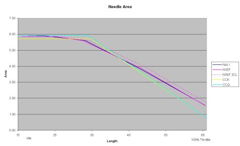
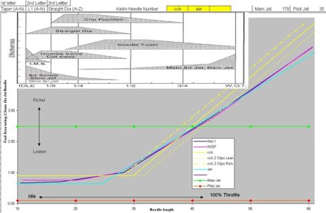
OK the graph is in effective fuel area. That means the orifice area (via main jet, pilot, needle jet etc) that the fuel can flow through to get into the air and make the air fuel mixture. For the needle and needle jet in particular this means the size of the needle jet minus the area of the needle that is in it. Although greatly simplified (the carb being much more complex that this with several other 'effects') it allows a rough comparison between the pilot, main and needle jet.
So with a larger area more fuel can flow through it and into the air (richer). Smaller area less fuel (leaner). I have also indicated 'richer and leaner' towards the left so if one line sits higher than another for example it is richer.
The spreadsheet can use any straight taper Keihin needle but at the moment I don't know how you calculate the complete diameter from NOZx needles and N1Ex needles. (perhaps someone can help?) I have measured via digital caliper the standard needle in my 05 Gas Gas EC 300 (N1EF) and a NOZI I had lying around to use these as a benchmark.
One of the Keihin needles always shows the effect of moving it 2 clips leaner or richer so you can see the effect of clip position on the fuel area – for other needle clip positions just imagine their line shifted the same amount right (leaner) or left (richer) .
I have overlaid the Keihin diagram showing fuelling effects of different carb aspects. I have scaled the X axis as accurately as I can at the moment so idle and 100% throttle on there correspond to idle and 100% throttle on my graph. You can ignore the graph after 53mm length as I believe this corresponds to 100 throttle though some subtle adjustments may be made in future.
There is a horizontal line for the area of the main jet – this becomes significant when the throttle is opened enough so that the effective fuel area of the needle jet approaches that of the main jet (where the lines cross) and the main jet will not allow much more fuel through even though the effective area of the needle jet is increasing. This is reflected in the Keihin diagram at the point where the main jet kicks up and becomes much more effective.
There is a horizontal line for the area of the pilot jet however this does not correspond well to the needle jet and transition between the two. The pilot area is about 6 time smaller than the needle jet area at idle and yet it is the pilot circuit that controls the air fuel ratio. This part I do not fully understand but believe it must be linked to the geometry of the carb in particular the semi-cylinder shape in front of the main jet exit, the way the slide covers this semi-cylinder and the different exit points for the pilot and main circuit. So all I can do here is refer to the Keilin diagram and notice where the pilot jet is effective and where the other effects take over i.e. throttle valve cutaway and straight diameter.
Another area that I do not fully understand is why the clip position is said to be so effective around ¼ throttle and not at higher throttle openings yet according to my calculations on the Keihin needles it is the straight diameter that affects the 'fuel area' around ¼ throttle. Even on Keilins website
http://www.keihin-us.com/am/_media/pdf/slide_valve.pdf at the top of page 2 is shows the clip position to greatly affect the 'needle diameter' upto WOT although of course the main jet will restrict the flow before WOT.
On a similar line why is the needle taper effective from 1/3 throttle yet my calculations show on most straight taper needles the taper only reaches the needle jet approaching ½ throttle (at which point their effectiveness is still zero but will increase from there).
So a few questions but a useful tool (I hope) to compare needles once I get the bugs ironed out and maybe make it easier to use anyone can have this for free. I say that as I believe this may be similar to other tools/spreadsheets (you would have to buy).
The next stage is to try and read people's needle/jetting reviews/comparisons to their 'feels smooth' can be tied up with being richer/leaner in certain areas…. Otherwise you need the experience to know where you want to be richer and leaner….
All comments welcome.


