You are using an out of date browser. It may not display this or other websites correctly.
You should upgrade or use an alternative browser.
You should upgrade or use an alternative browser.
Complete Rebuild - EC250
- Thread starter RockefellerGG
- Start date
RockefellerGG
New member
Ignition Reassembly
Re-Assembling this is a lot of the same thing, but in reverse. I took some pictures which may be redundant.
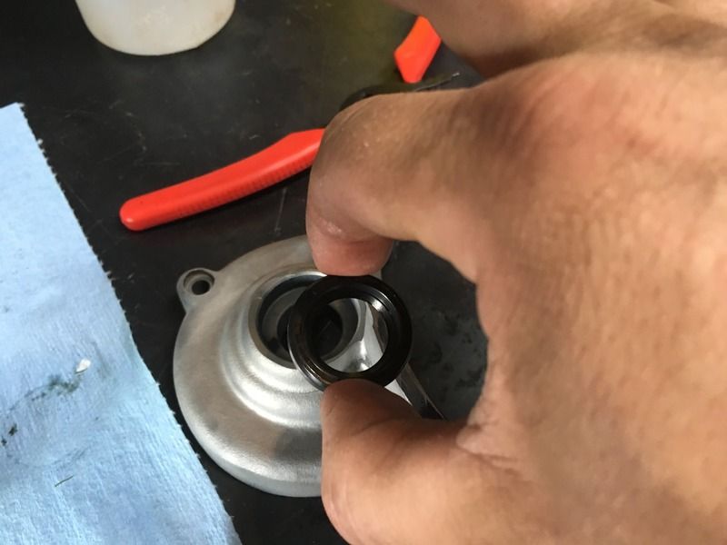
Ignition Reassembly. Line up the marks to put it back close to how it came out. Made sure the rubber seals are nice and tight and back in their homes:
8 Nm Torgue
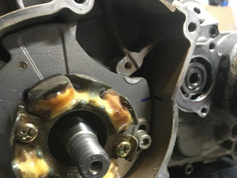
Threadlocker on the crank and 40 Nm on the nut:
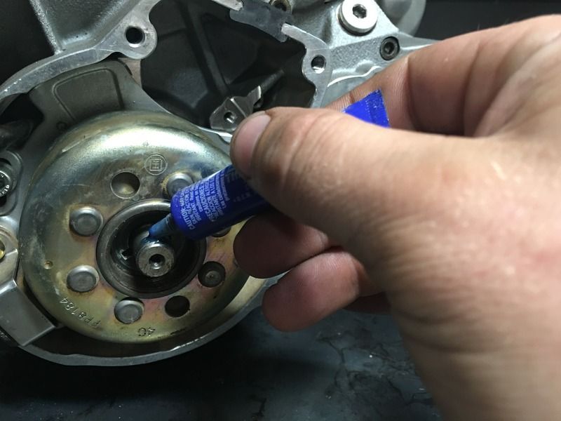
I'm leaving the cover off for now, so that I can use the nut to turn the engine over during squish measurements.
Re-Assembling this is a lot of the same thing, but in reverse. I took some pictures which may be redundant.
Ignition Reassembly. Line up the marks to put it back close to how it came out. Made sure the rubber seals are nice and tight and back in their homes:
8 Nm Torgue

Threadlocker on the crank and 40 Nm on the nut:

I'm leaving the cover off for now, so that I can use the nut to turn the engine over during squish measurements.
RockefellerGG
New member
RockefellerGG
New member
RockefellerGG
New member
BTW - I like to oil the seals when putting them in. Helps them stay in shape and not tear.
RockefellerGG
New member
Flywheel
Don't forget the crankshaft o-ring: I forgot this and had to crack the cover back off take it apart and add mine:
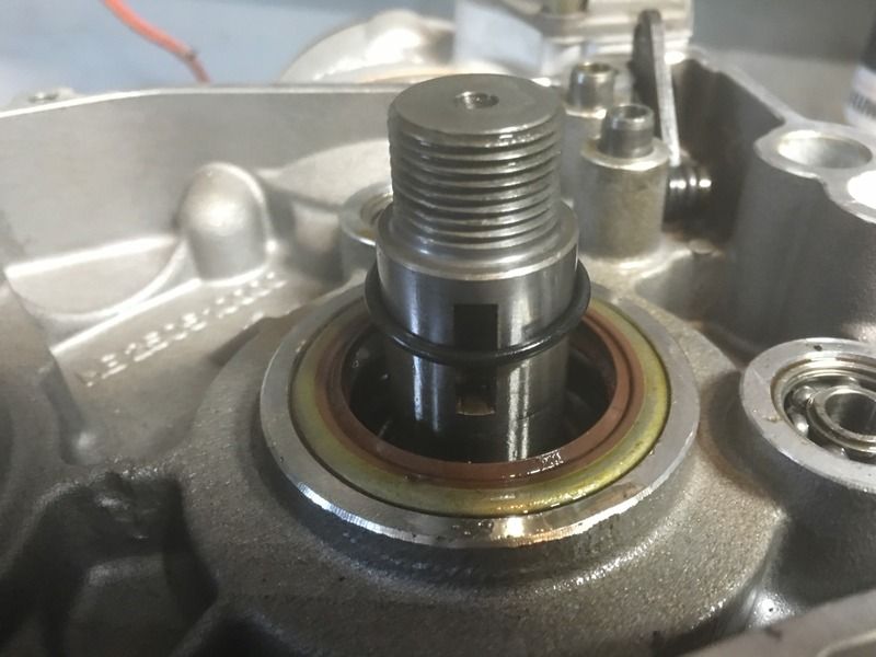
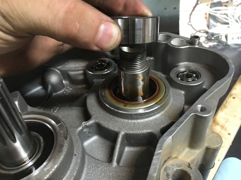
Crank spacer installed carefully so as not to damage the seal. Machined flat side up:
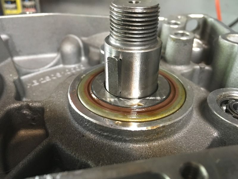
Put the key lock back in:
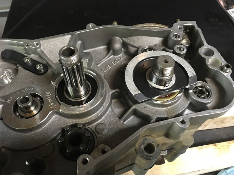
Flywheel:
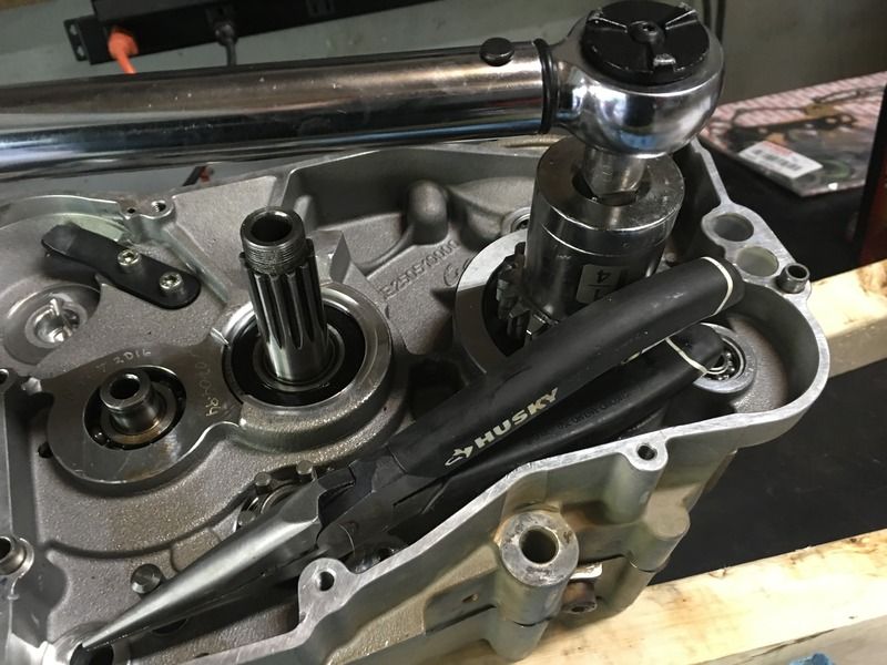
Add the crank gear,washer and nut. I used the rubber side of a pair of needle nose to block the flywheel from turning. This is Lefty-Tighty. 40 Nm:
Don't forget the crankshaft o-ring: I forgot this and had to crack the cover back off take it apart and add mine:

Crank spacer installed carefully so as not to damage the seal. Machined flat side up:

Put the key lock back in:

Flywheel:

Add the crank gear,washer and nut. I used the rubber side of a pair of needle nose to block the flywheel from turning. This is Lefty-Tighty. 40 Nm:

Last edited:
RockefellerGG
New member
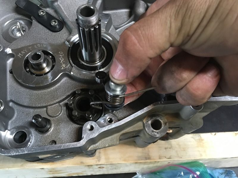
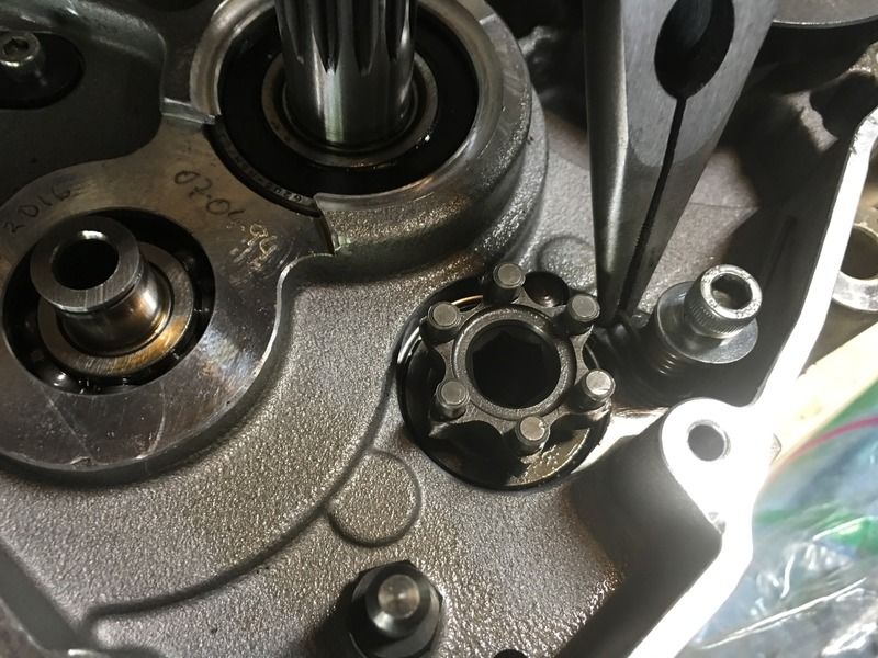
Install the shift selector. There's a trick to this. 1. Release the tension from the spring, so that the hook is on the left side of the plate. 2. Very loosely install the bolt. 3) Lift the spring hooked side over the plate and hook it over the right side. Then tighten the bolt. 15 Nm
See how the hook is on the left side:
Lift the spring up and over and hook it over the right side:
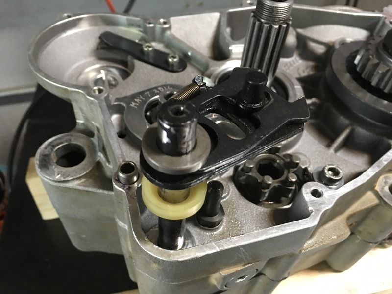
Slide the shift selector shaft back through the engine case. Remember to add the white plastic bushing. Curved side up:
Add the spring:
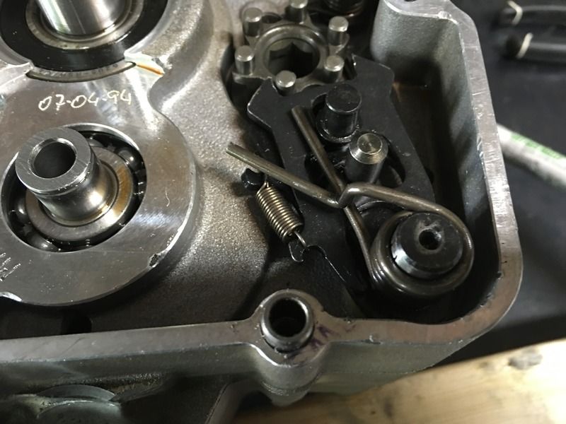
Lift the curved end of the spring up and over the post to pre-load the spring.
See how the hook is on the left side:

Lift the spring up and over and hook it over the right side:

Slide the shift selector shaft back through the engine case. Remember to add the white plastic bushing. Curved side up:

Add the spring:

Lift the curved end of the spring up and over the post to pre-load the spring.
RockefellerGG
New member
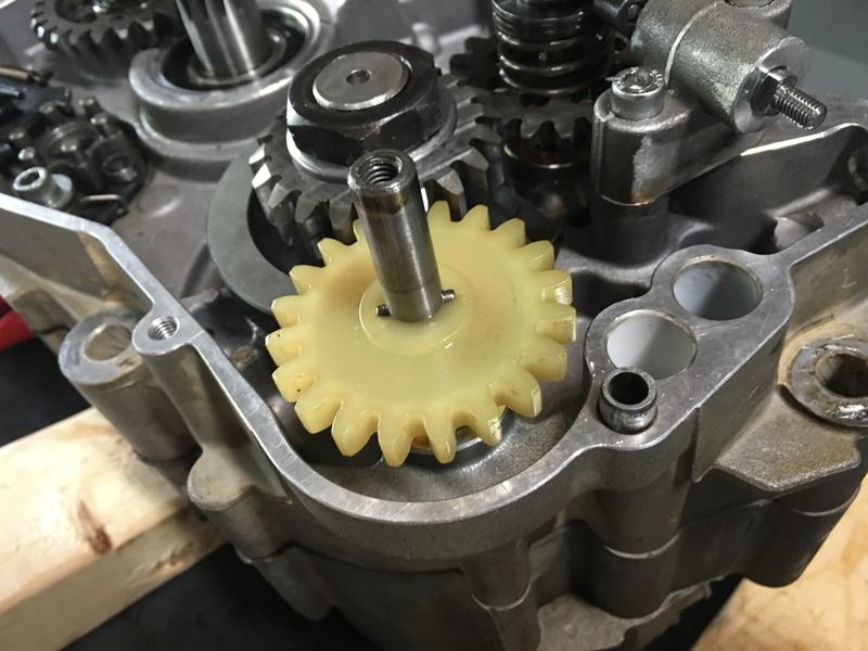
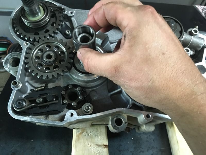
Place the starter gears into the case:
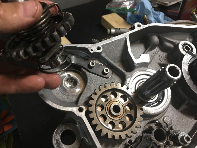
Re-tension the spring by placing the end back into the hole:
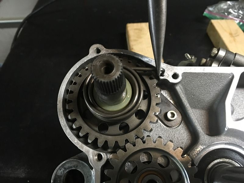
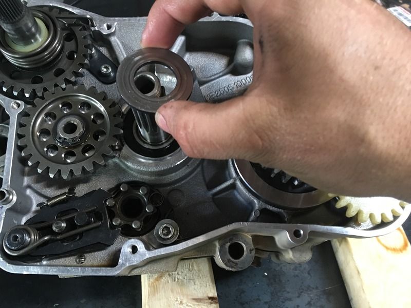
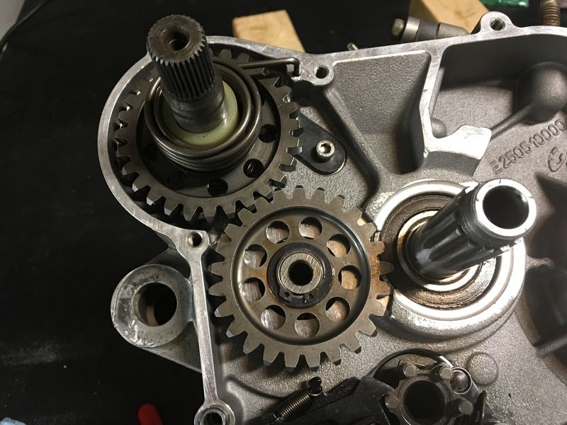
Add the washer and c-clip on the counter gear:
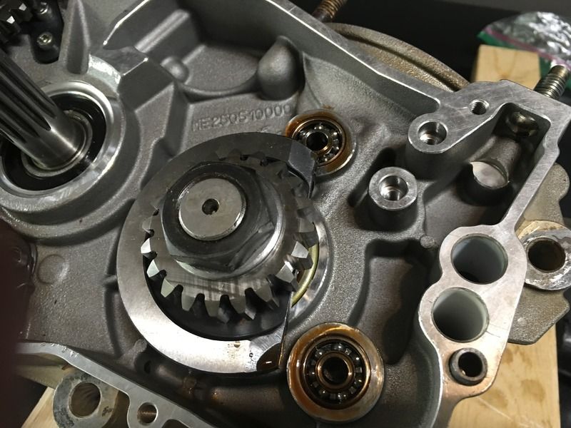
Lubricated the new bearings:
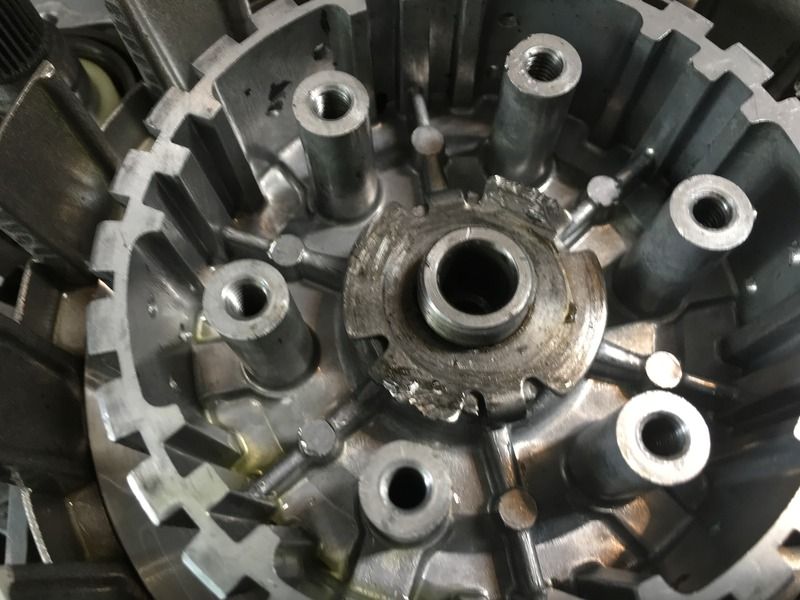
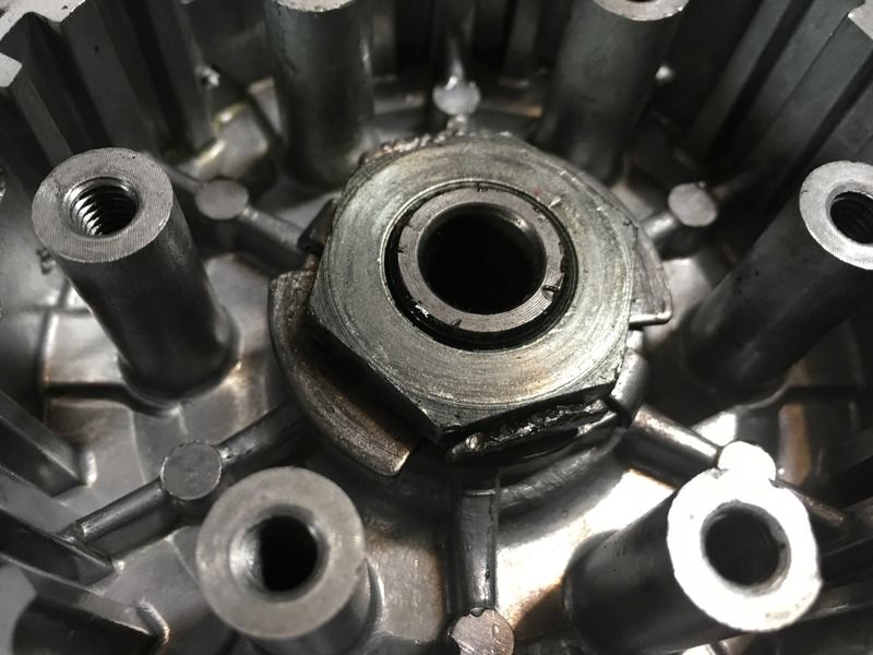
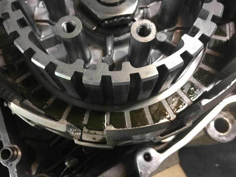
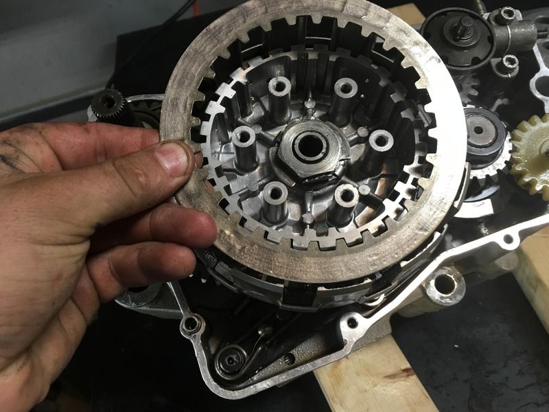
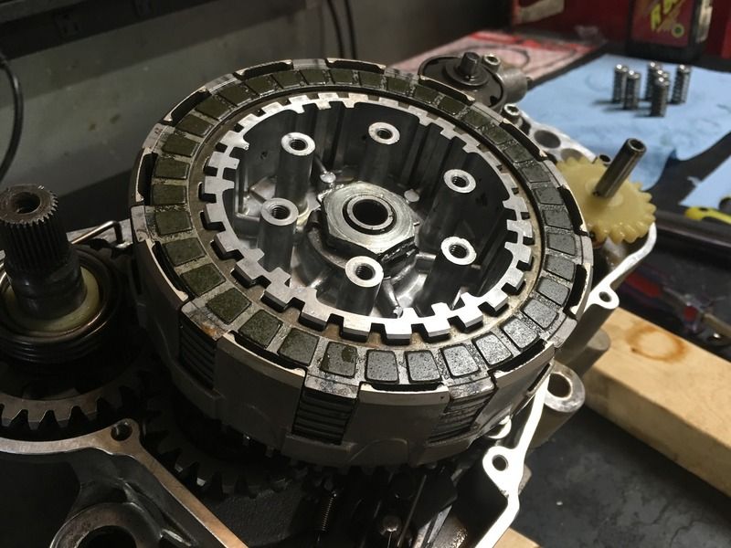
Reinstall the centrifugal assembly:
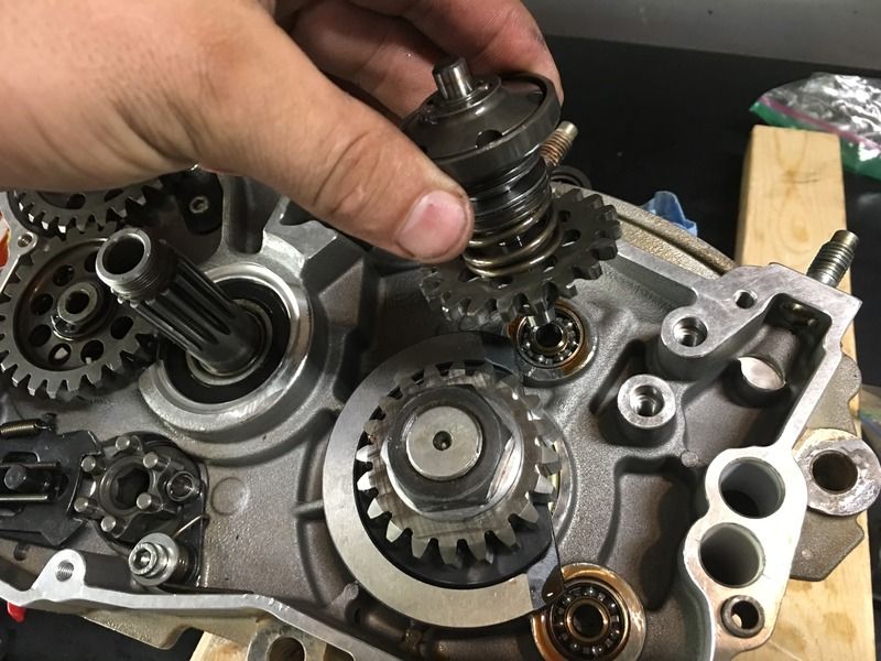
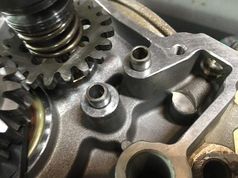
Put the alignment pins back in:
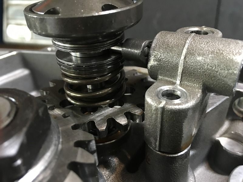
Re-install the support block back into the engine. Making sure to put the pin in the slot between the shims. Bolts tightened to 10 Nm:

Re-tension the spring by placing the end back into the hole:

Add the washer and c-clip on the counter gear:

Lubricated the new bearings:

Reinstall the centrifugal assembly:

Put the alignment pins back in:

Re-install the support block back into the engine. Making sure to put the pin in the slot between the shims. Bolts tightened to 10 Nm:

RockefellerGG
New member
RockefellerGG
New member
RockefellerGG
New member
RockefellerGG
New member
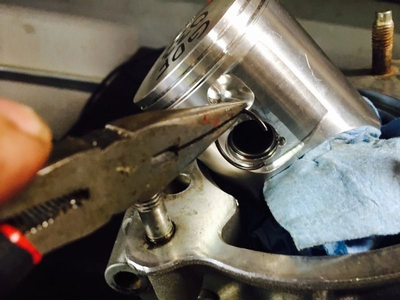
I should have said this a while ago, but keep a rag in the case opening. You DO NOT want to drop a clip, nut, or bolt down the hole.
Install the connecting rod needle bearing:
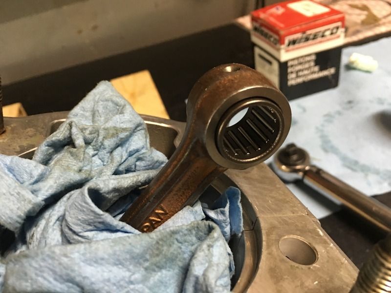
Place the piston on the connecting rod with the arrow on top of the piston facing the front of the engine. Slide the wrist pin through:
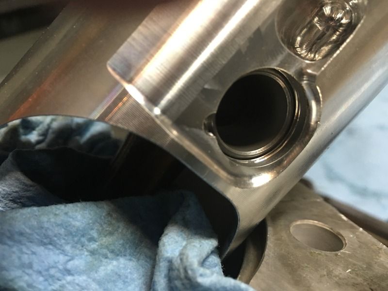
Insert the circle clips on each end of the wrist pin:
Install the connecting rod needle bearing:

Place the piston on the connecting rod with the arrow on top of the piston facing the front of the engine. Slide the wrist pin through:

Insert the circle clips on each end of the wrist pin:

RockefellerGG
New member
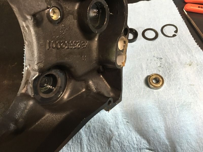
I'm using fine glass in the blasting cabinet. The powervalve parts were all black with carbon build up. The bearings were very rough and I just replaced them.
FYI - check out skate/rollerblade bearings for the power valve and right side cover. I removed one metal seal from the bearing, like the ones that came on the engine. I think I got 8 bearings for $10 on Amazon Now. Free shipping and at my door in less than an hour.
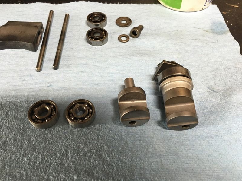
FYI - check out skate/rollerblade bearings for the power valve and right side cover. I removed one metal seal from the bearing, like the ones that came on the engine. I think I got 8 bearings for $10 on Amazon Now. Free shipping and at my door in less than an hour.

RockefellerGG
New member
Ha!
Select cities across the country have amazon distribution centers that offer the Prime Now service. They have drivers that pick and deliver orders in ordinary vehicles and bring them to the door.
Tips are recommended... the selection is much more limited, but still a nice option.
Select cities across the country have amazon distribution centers that offer the Prime Now service. They have drivers that pick and deliver orders in ordinary vehicles and bring them to the door.
Tips are recommended... the selection is much more limited, but still a nice option.
RockefellerGG
New member
I used the RB instructions for measuring squish:
http://www.gasgasrider.org/html/measuring_squish.html
Installed the piston rings:
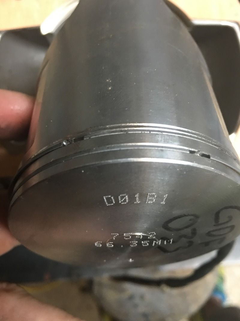
Placed a base gasket and head on the engine. I used a new gasket, it was all I had. The first time through, I used the 0.5mm gasket and the second time, I used the 0.3mm gasket:
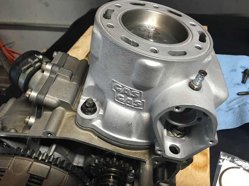
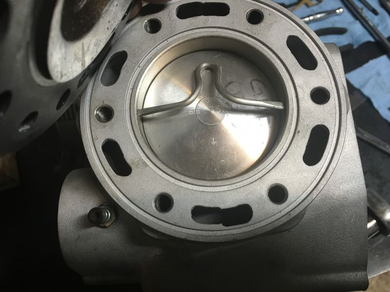
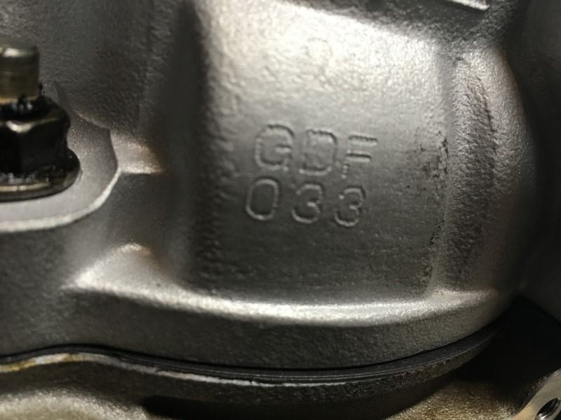
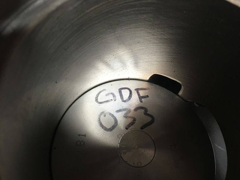
Notice that the machine shop matched the new cylinder/coating to the piston:
http://www.gasgasrider.org/html/measuring_squish.html
Installed the piston rings:

Placed a base gasket and head on the engine. I used a new gasket, it was all I had. The first time through, I used the 0.5mm gasket and the second time, I used the 0.3mm gasket:

Notice that the machine shop matched the new cylinder/coating to the piston:


RockefellerGG
New member
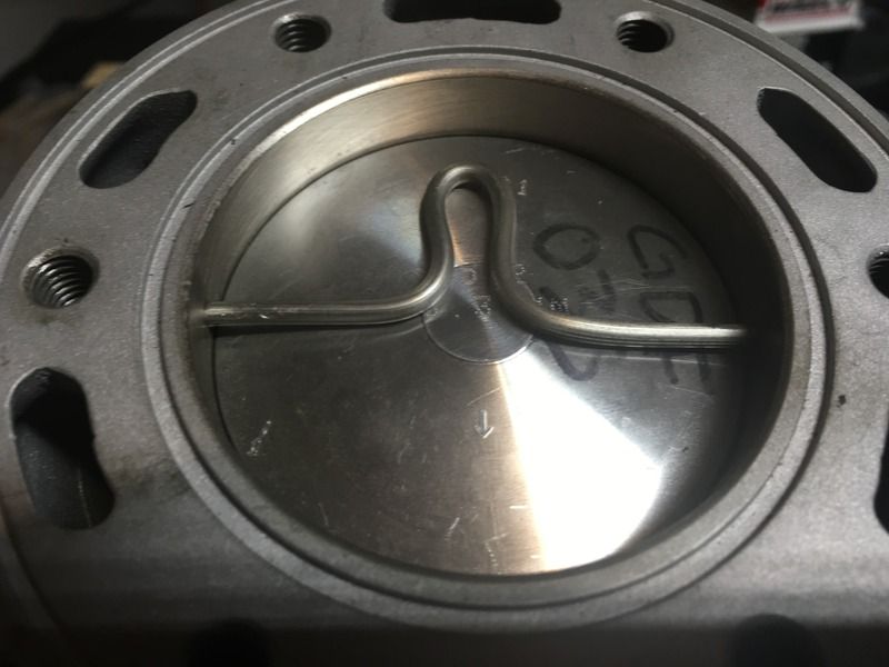
I cut two pieces of 3mm solder. Cutting the ends with a razor blade and filing the ends square:
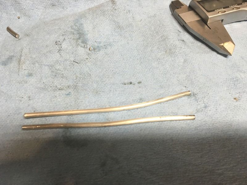
Bent them into this shape, with the squared off ends touching the 3 o'clock and 9 o'clock positions of the cylinder.
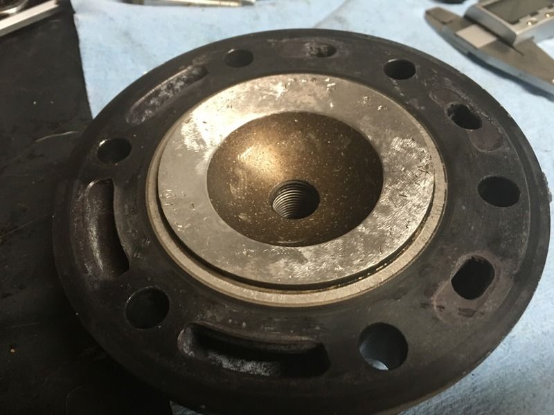
The gouges in the head were cleaned up by Hall's Cycles. Not a perfect machined squish band or dome, but it is a huge improvement over the damage it had:
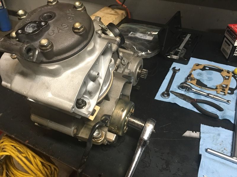
Without the head's o-rings, I installed the head and using the crank bolt, turned the engine over a couple times to flatten the solder:

Bent them into this shape, with the squared off ends touching the 3 o'clock and 9 o'clock positions of the cylinder.

The gouges in the head were cleaned up by Hall's Cycles. Not a perfect machined squish band or dome, but it is a huge improvement over the damage it had:

Without the head's o-rings, I installed the head and using the crank bolt, turned the engine over a couple times to flatten the solder:

RockefellerGG
New member
RockefellerGG
New member
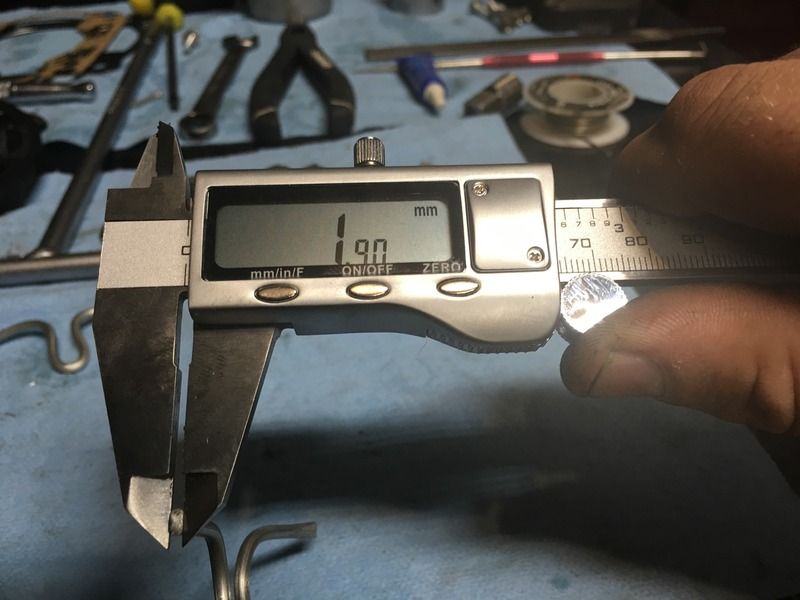
The squish gap seems pretty high. With the 0.5mm gasket, it was even bigger. This sounds like it is within spec, but far from optimum. I suppose I could throw on the 0.15mm gasket, but how much would that impact port timing?
I need to talk to the bike owner and see if he wants to send the head off to Ron Black. This would be the perfect time to do it.
I need to talk to the bike owner and see if he wants to send the head off to Ron Black. This would be the perfect time to do it.
Similar threads
- Replies
- 3
- Views
- 3K
- Replies
- 9
- Views
- 4K
- Replies
- 13
- Views
- 5K

