re assurance needed

Rabbitist

New member
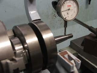
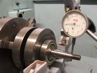
ok guys the crank is pressed back together and these measurements were taken using a surface table precision magnetic vee's and .0001" clocks i have knocked the crank fairly true here are the videos of both trueness and swash please watch these and tell me if this is acceptable??? the factory manual says 2tho (.002") is alowed on both journals and swash so am i doing this right? please will someone with the knowledge re assure me.. any way heres the links to my videos the journal trueness is .0008" and the swash is .0015"

http://www.youtube.com/watch?v=gQYj...DvjVQa1PpcFN9JkC9CjbnJzQl9gzsttztyiStvKBXWGM=

http://www.youtube.com/watch?v=FTiK...DvjVQa1PpcFN9JkC9CjbnJzQl9gzsttztyiStvKBXWGM=
 
Well that's a different way of looking at it. You are using the V block to reference the crank wheels and then measure the shafts. I'm used to using a roller stand with the rollers up close to the crank wheels (main bearing seats) and then measuring out at the shaft ends. Do you get the same runout at the mains and out at the shaft ends? This would verify that the shafts are parallel with each other.

Can you put it "between centers" to verify your runout? Just enough tailstock pressure to very lightly keep the crank in place. Then compare runout at the mains locations and on the crank wheels. If it matches the V block measurements, you've got it right.

I think most guys use a vernier to measure across the crank cheeks (as for the assembly dimension) and just compare this at several locations. The idea is to have the mains locations and shaft ends as true and parallel as possible so the main bearings don't fight each other.

Your .0008 measurement for runout is great. Anytime you get below one thou it's a good assembly job.
 
Here is how I did mine - it turned out within 0.01mm;)
 

Attachments

  • 16-photos 017.jpg
    16-photos 017.jpg
    19.9 KB · Views: 30
thanks guys found a great bit of kit on one of our longbed mullers that is used for setting the reamers on rotors a little 20" centres with two micron clocks attached.. after banging it about a bit more i have managed to get it within .03mm (30 microns) on the journals .. the shafts that run the fly wheel and other side are within a few microns and the swash within a 25 microns.. i have just clocked on top of the cheeks out of interest and they are running 8 tho out i guess this doesnt matter so much as the journals are whats important and a ground finish were as the top of the cheeks is rougher
 
Good work. If the shafts run true (and parallel) you're done. I would expect the crank wheels to run only a few thou different since they are machined integral with the shafts.

You can always chuck a piece of steel and machine a point on it. Once "machined in place" it is "true" to the headstock bearings. A dab of grease is good enough for turning the crank to get an indicator reading.

I'm always suspicious of chucking on one shaft and indicating the other. Most jaws have a bit of wear and don't center perfectly. A brand new chuck might be good. A collet should be fine; depends on the machine.

Runout on the crank cheeks could create some vibration. Is there a shop nearby that can check the balancing for you? I don't know what the process is, maybe all the parts would have to be weighed before assembly.
 
thanks the crank is from an old engine with the counterbalance shaft that runs through the casing so hopefully any vibration will be dealt with that way..
 
We are at the mercy of the quality of the parts whichever way we check the runout. It's only ever going to get "so good". Here is a pic of the truing stand I made up. My theory was that I could check everything in one setup by using a roller stand and measuring everything relative to the main bearing locations.

picture.php
 
Nice bit of kit! I now have tge crank back in but it seems to have a right spot when the pin is at bottom dead centre???
 
The most likely scenario is that the cases weren't hot enough when you assembled and the crank was "pinched" as you bolted it up. If the engine cools before the center gasket is compressed the bolting force pushes on the bearings which in turn push on the crank.

That's the main reason I like roller bearing cranks as they are so easy to install. An engine design that uses sealer on the case joint is better than than one using a gasket. No need to factor gasket crush into the assembly dimensions.

Can you mount an indicator to the cases and look at the runout at various locations? This might tip you off to how it's moved. The normal thing is for the crank wheels to tilt in opposite the big end pin. In the old days, a shop would use a tool that looks like the claw end of a hammer with a T handle welded to it. That would be inserted in the gap and twisted to spread the crank cheeks back apart.

I suggest you take the cases apart and investigate. Better to be sure what's going on now instead of after it is all together with a potential problem. This type of work takes great patience.
 
Back
Top